The Three-Pole Electromagnet
advertisement
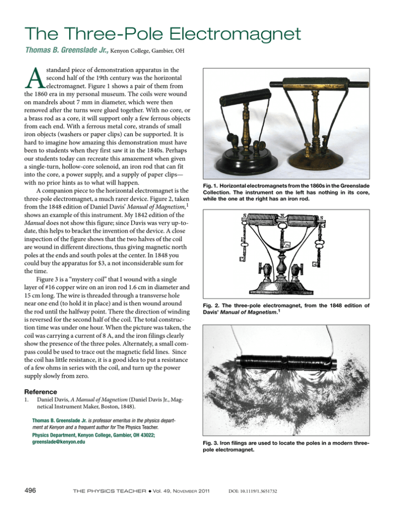
The Three-Pole Electromagnet Thomas B. Greenslade Jr., Kenyon College, Gambier, OH A standard piece of demonstration apparatus in the second half of the 19th century was the horizontal electromagnet. Figure 1 shows a pair of them from the 1860 era in my personal museum. The coils were wound on mandrels about 7 mm in diameter, which were then removed after the turns were glued together. With no core, or a brass rod as a core, it will support only a few ferrous objects from each end. With a ferrous metal core, strands of small iron objects (washers or paper clips) can be supported. It is hard to imagine how amazing this demonstration must have been to students when they first saw it in the 1840s. Perhaps our students today can recreate this amazement when given a single-turn, hollow-core solenoid, an iron rod that can fit into the core, a power supply, and a supply of paper clips— with no prior hints as to what will happen. A companion piece to the horizontal electromagnet is the three-pole electromagnet, a much rarer device. Figure 2, taken from the 1848 edition of Daniel Davis’ Manual of Magnetism,1 shows an example of this instrument. My 1842 edition of the Manual does not show this figure; since Davis was very up-todate, this helps to bracket the invention of the device. A close inspection of the figure shows that the two halves of the coil are wound in different directions, thus giving magnetic north poles at the ends and south poles at the center. In 1848 you could buy the apparatus for $3, a not inconsiderable sum for the time. Figure 3 is a “mystery coil” that I wound with a single layer of #16 copper wire on an iron rod 1.6 cm in diameter and 15 cm long. The wire is threaded through a transverse hole near one end (to hold it in place) and is then wound around the rod until the halfway point. There the direction of winding is reversed for the second half of the coil. The total construction time was under one hour. When the picture was taken, the coil was carrying a current of 8 A, and the iron filings clearly show the presence of the three poles. Alternately, a small compass could be used to trace out the magnetic field lines. Since the coil has little resistance, it is a good idea to put a resistance of a few ohms in series with the coil, and turn up the power supply slowly from zero. Fig. 1. Horizontal electromagnets from the 1860s in the Greenslade Collection. The instrument on the left has nothing in its core, while the one at the right has an iron rod. Fig. 2. The three-pole electromagnet, from the 1848 edition of Davis’ Manual of Magnetism.1 Reference 1. Daniel Davis, A Manual of Magnetism (Daniel Davis Jr., Magnetical Instrument Maker, Boston, 1848). Thomas B. Greenslade Jr. is professor emeritus in the physics department at Kenyon and a frequent author for The Physics Teacher. Physics Department, Kenyon College, Gambier, OH 43022; greenslade@kenyon.edu 496 Fig. 3. Iron filings are used to locate the poles in a modern threepole electromagnet. The Physics Teacher ◆ Vol. 49, November 2011 DOI: 10.1119/1.3651732
