Chapter 4 Shear Forces and Bending Moments
advertisement

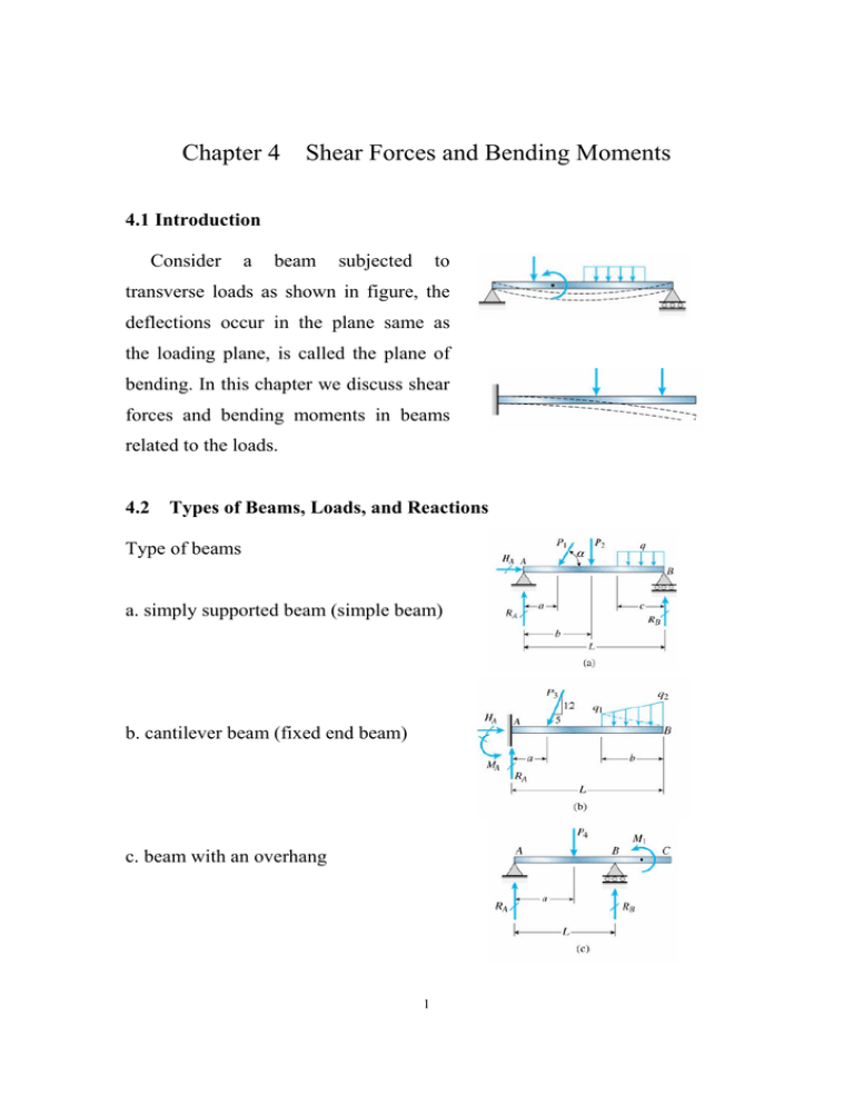
Chapter 4 Shear Forces and Bending Moments 4.1 Introduction Consider a beam subjected to transverse loads as shown in figure, the deflections occur in the plane same as the loading plane, is called the plane of bending. In this chapter we discuss shear forces and bending moments in beams related to the loads. 4.2 Types of Beams, Loads, and Reactions Type of beams a. simply supported beam (simple beam) b. cantilever beam (fixed end beam) c. beam with an overhang 1 Type of loads a. concentrated load (single force) b. distributed load (measured by their intensity) : uniformly distributed load (uniform load) linearly varying load c. couple Reactions consider the loaded beam in figure equation of equilibrium in horizontal direction Fx = 0 HA HA MB = 0 P1 cos = 0 = P1 cos - RA L + (P1 sin ) (L - a) + P2 (L - b) + q c2 / 2 = 0 RA (P1 sin ) (L - a) = CCCCCCC L RB (P1 sin ) a = CCCCC L + + P2 b CC L P2 (L - b) CCCC + L + q c2 CC 2L for the cantilever beam Fx = Fy = 0 0 HA = 5 P3 / 13 12 P3 RA = CC + 13 (q1 + q2) b CCCCC 2 2 q c2 CC 2L MA = 0 12 P3 q1 b q1 b MA = CC + CC (L – 2b/3) + CC (L – b/3) 13 2 2 for the overhanging beam MB = 0 - RA L + P4 (L– a) + M1 = 0 MA = 0 - P4 a + RB L + M1 = 0 P4 (L– a) + M1 RA = CCCCCC L 4.3 P4 a - M1 RB = CCCC L Shear Forces and Bending Moments Consider a cantilever beam with a concentrated load P applied at the end A, at the cross section mn, the shear force and bending moment are found Fy = 0 V = P M 0 M = Px = sign conventions (deformation sign conventions) the shear force tends to rotate the material clockwise is defined as positive the bending moment tends to compress the upper part of the beam and elongate the lower part is defined as positive 3 Example 4-1 a simple beam AB M0, and a couple bending moment (a) at (b) M0 C L - x = Fy = V M = (b) at = at x = (L/2)+ P RB = C 4 RA RA 0 M and M0 C L + (L/2)_ 0 = V P at x = (L/2)_ at Example find the shear M 3P RA = C 4 (a) supports a force - P - V = 0 - P = -P/4 - M0 / L - RA (L/2) + P (L/4) + M = RA (L/2) + P (L/4) x = (L/2)+ V = - P / 4 - M0 / L M = P L / 8 + M0 / 2 = P L / 8 - M0 / 2 [similarly as (a)] 4-2 a cantilever beam AB subjected to a linearly varying distributed load as shown, find the shear force V and the bending moment q M = q0 x / L Fy = V = Vmax - V - 2 (q0 x / L) (x) 0 - q0 x2 / (2 L) = - q0 L / 2 4 0 = 0 M = M 0 M = - q0 L 2 / 6 Mmax 4-3 an overhanging beam supported to an uniform load q ABC the shear force M V at is of intensity and a concentrated load P, moment 0 - q0 x3 / (6 L) = Example 2 (q0 x / L) (x) (x / 3) = + calculate and the bending D from equations of equilibrium, it is found RA = 40 kN RB = 48 kN at section D Fy = 0 40 - 28 - 6 x 5 - V = 0 V = M = - 18 kN 0 - 40 x 5 + 28 x 2 + 6 x 5 x 2.5 + M = 0 M = 69 kN-m from the free body diagram of the right-hand part, same results can be obtained 4.4 Relationships Between Loads, Shear Forces, and Bending Moments consider an element of a beam of length dx subjected to distributed loads q equilibrium of forces in vertical direction 5 Fy = 0 V - q dx - (V + dV) or dV / dx = B 0 -q integrate between two points A and ∫ dV = B B = -∫ q dx A A i.e. B VB - VA = = -∫ q dx A - (area of the loading diagram between A and B) the area of loading diagram may be positive or negative moment equilibrium of the element M = 0 - M - q dx (dx/2) - (V + dV) dx + M + dM or dM / dx = = 0 V maximum (or minimum) bending-moment occurs at dM / dx i.e. at the point of shear force V = B A 0, 0 integrate between two points A and ∫ dM = = B B ∫ V dx A i.e. B MB - MA = = ∫ V dx A (area of the shear-force diagram between A and B) this equation is valid even when concentrated loads act on the beam between and A and B, but it is not valid if a couple acts between B 6 A concentrated loads equilibrium of force V - or P - (V + V1) V1 = = 0 -P i.e. an abrupt change in the shear force occurs at any point where a concentrated load acts equilibrium of moment - M - P (dx/2) or M1 = since the length - P (dx/2) dx (V + V1) dx + V dx + M + + V1 dx j M1 = 0 0 of the element is infinitesimally small, i.e. M1 is also infinitesimally small, thus, the bending moment does not change as we pass through the point of application of a concentrated load loads in the form of couples equilibrium of force V1 = 0 i.e. no change in shear force at the point of application of a couple equilibrium of moment - M + M0 - (V + V1) dx + M + M1 or M1 = = 0 - M0 the bending moment changes abruptly at a point of application of a couple 7 4.5 Shear-Force and Bending-Moment Diagrams concentrated loads consider a simply support beam AB with a concentrated load P RA = for Pb/L 0 < x < V = RA = M = RA x note that for RB a < Pa/L a Pb/L = Pbx/L dM / dx = x < = RA - P M = RA x note that Mmax Pb/L = V L V with = = -Pa/L - P (x - a) dM / dx = = = P a (L - x) / L -Pa/L Pab/L uniform load consider a simple beam AB with a uniformly distributed load of constant intensity q 8 = V RA V = = RB = qL/2 RA - q x = qL/2 -qx M = RA x - q x (x/2) = q L x / 2 - q x2 / 2 note that dM / dx = q L / 2 - q x / 2 = V Mmax q L2 / 8 = at x = L/2 several concentrated loads for 0 < x < a1 V = RA = M1 for a1 < x < a2 M RA a 1 V = M = RA x = RA x M2 - M1 = RA - P1 - P1 (x - a1) (RA - P1 )(a2 - a1) similarly for others M2 = Mmax Example because V = 0 at that point 4-4 construct the shear-force and bending -moment diagrams for the simple beam AB RA = q b (b + 2c) / 2L RB = q b (b + 2a) / 2L for 0 < x < a V = RA M = RA x 9 for for a < x < a V = RA M = RA x a + b < x V = - RB + b - q (x - a) - q (x - a)2 / 2 < L M = RB (L - x) maximum moment occurs where V i.e. x1 = Mmax for a = b = L, b (b + 2c) / 2L x1 = = L/2 q b (2L - b) / 8 a=c=0 Mmax Example + (uniform loading over the entire span) = q L2 / 8 V- and 4-5 construct the M-dia for the cantilever beam supported to P1 RB = P1 + P2 for for 0 q b (b + 2c) (4 a L + 2 b c + b2) / 8L2 = c, Mmax for a = 0 < x < V = - P1 a < x V = - P1 = - P1 x and P2 MB = P1 L + P2 b a M = - P1 x < L - P2 M - P2 (x - a) 10 Example 4-6 construct the V- and M-dia for the cantilever beam supporting to a constant uniform load of intensity RB q = then V qL = MB -qx = M q L2 / 2 - q x2 / 2 = Mmax = - q L2 / 2 Vmax = - q L alternative method x = V-0 = V V - VA = -∫ q dx x M - MA = M - 0 Example = M = -∫ V dx 0 4-7 an overhanging beam is subjected to a uniform load of and a couple q M0 = = 1 kN/m on AB 12 kN-m on midpoint of BC, construct the V- and M-dia for the beam RB = 5.25 kN RC = 1.25 kN on AB shear force diagram V = = -qx 0 -qx V = constant on BC 11 = - q x2 / 2 bending moment diagram MB = - q b2 / 2 = the slope of M on just to the left of M0 M = - 1 x 42 / 2 = - 8 kN-m BC is constant (1.25 kN), the bending moment is - 8 + 1.25 x 8 = 2 kN-m the bending moment just to the right of M0 M = 2 - 12 = - is 10 kN-m and the bending moment at point C is MC = - 10 + 1.25 x 8 = 0 12 as expected


