D192D
Module
Indicating Circuit Supervision
Features
•
Compatible with 12 or 24 V DC
Control/Communicators
•
Supervises 12 or 24 V DC Class A, Style Z or
Class B, Style Y indicating circuits
•
Supervised signal silencing switch
•
Signaling circuit rated at 3 Amps
•
Multiple module configurations
•
Mounts in panel enclosure
Description
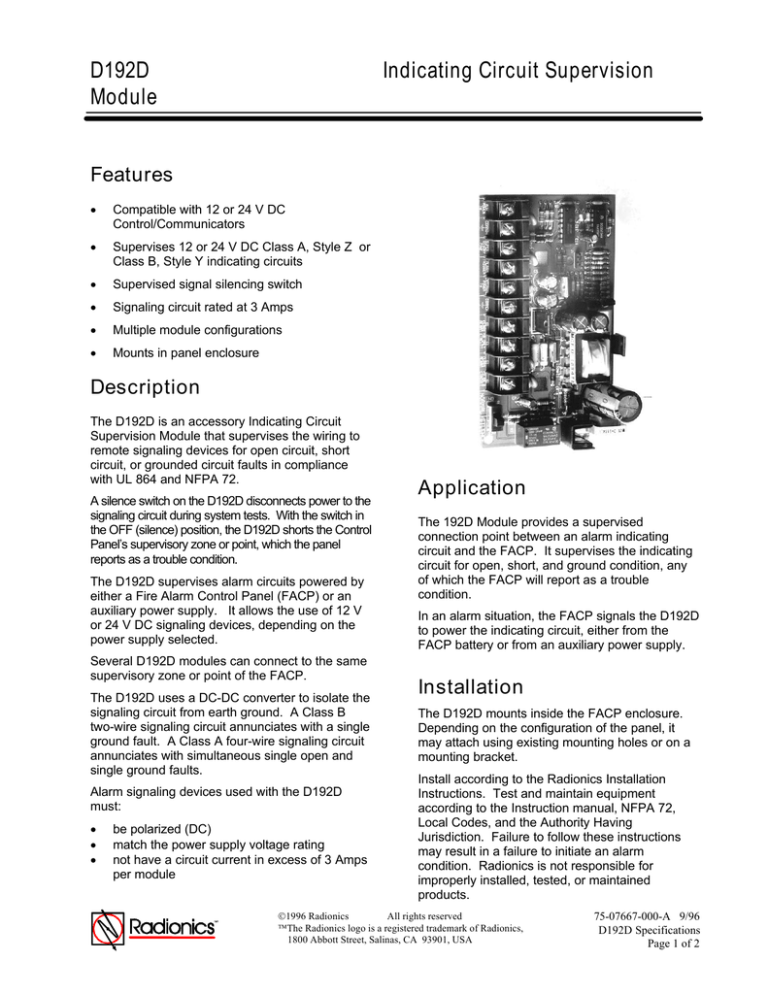
The D192D is an accessory Indicating Circuit
Supervision Module that supervises the wiring to
remote signaling devices for open circuit, short
circuit, or grounded circuit faults in compliance
with UL 864 and NFPA 72.
A silence switch on the D192D disconnects power to the
signaling circuit during system tests. With the switch in
the OFF (silence) position, the D192D shorts the Control
Panel’s supervisory zone or point, which the panel
reports as a trouble condition
The D192D supervises alarm circuits powered by
either a Fire Alarm Control Panel (FACP) or an
auxiliary power supply. It allows the use of 12 V
or 24 V DC signaling devices, depending on the
power supply selected.
Several D192D modules can connect to the same
supervisory zone or point of the FACP.
The D192D uses a DC-DC converter to isolate the
signaling circuit from earth ground. A Class B
two-wire signaling circuit annunciates with a single
ground fault. A Class A four-wire signaling circuit
annunciates with simultaneous single open and
single ground faults.
Alarm signaling devices used with the D192D
must:
•
•
•
be polarized (DC)
match the power supply voltage rating
not have a circuit current in excess of 3 Amps
per module
Application
The 192D Module provides a supervised
connection point between an alarm indicating
circuit and the FACP. It supervises the indicating
circuit for open, short, and ground condition, any
of which the FACP will report as a trouble
condition.
In an alarm situation, the FACP signals the D192D
to power the indicating circuit, either from the
FACP battery or from an auxiliary power supply.
Installation
The D192D mounts inside the FACP enclosure.
Depending on the configuration of the panel, it
may attach using existing mounting holes or on a
mounting bracket.
Install according to the Radionics Installation
Instructions. Test and maintain equipment
according to the Instruction manual, NFPA 72,
Local Codes, and the Authority Having
Jurisdiction. Failure to follow these instructions
may result in a failure to initiate an alarm
condition. Radionics is not responsible for
improperly installed, tested, or maintained
products.
1996 Radionics
All rights reserved
The Radionics logo is a registered trademark of Radionics,
1800 Abbott Street, Salinas, CA 93901, USA
75-07667-000-A 9/96
D192D Specifications
Page 1 of 2
Dimensions
Specifications
12 V
24 V
10.0 - 14.0 V DC
17.0 - 28.0 V DC
1 mA
2 mA
Auxiliary Power
Alarm Current
70 mA
70 mA
External Power
Input Current
1.25 x Signaling
Circuit Current
1.25 x Signaling
Circuit Current
Signaling
Circuit Current
Rating
Compatible
0.1 A Minimum
3.0 A Maximum
0.1 A Minimum
3.0 A Maximum
Alarm-SAF ASPS5-BFS-12-UL
Radionics D9142F
Alarm-SAF ASPS5-BFS-24-UL
D192D
Input Voltage
(Auxiliary or
External)
Auxiliary Power
Idle Current
External Power
Supplies
•
•
•
Width
Height
Depth
3”
5”
2”
Ordering Information
Model
D192D
Description
Indicating Circuit Supervision Module
•
Class B +
Class A +
Class B -
Class A -
Class A Class A +
•
•
Class A Circuit Connections
Class B Circuit Connections
The Class B Circuit must have a 33k End of
Line resistor installed in the circuit after the last
signaling device..
1996 Radionics
All rights reserved
The Radionics logo is a registered trademark of Radionics,
1800 Abbott Street, Salinas, CA 93901, USA
75-07667-000-A 9/96
D192D Specifications
Page 2 of 2


