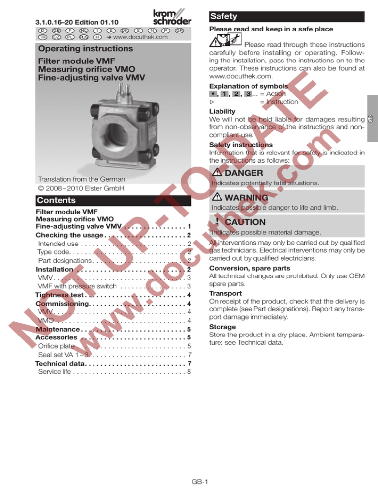
VMF, VMO, VMV
advertisement

Safety 3.1.0.16–20 Edition 01.10 GB F NL I CZ PL RUS H E DK S N P Please read and keep in a safe place GR ➔ www.docuthek.com Please read through these instructions carefully before installing or operating. Following the installation, pass the instructions on to the operator. These instructions can also be found at www.docuthek.com. Explanation of symbols • , , , ...= Action ▷ = Instruction Liability We will not be held liable for damages resulting from non-observance of the instructions and noncompliant use. Safety instructions Information that is relevant for safety is indicated in the instructions as follows: Operating instructions D Filter module VMF Measuring orifice VMO Fine-adjusting valve VMV DANGER Translation from the German © 2008 – 2010 Elster GmbH Indicates potentially fatal situations. WARNING Contents Filter module VMF Measuring orifice VMO Fine-adjusting valve VMV . . . . . . . . . . . . . . . . . 1 Checking the usage . . . . . . . . . . . . . . . . . . . . 2 Intended use . . . . . . . . . . . . . . . . . . . . . . . . . . . . 2 Type code . . . . . . . . . . . . . . . . . . . . . . . . . . . . . . 2 Part designations . . . . . . . . . . . . . . . . . . . . . . . . 2 Installation . . . . . . . . . . . . . . . . . . . . . . . . . . . . 2 VMV . . . . . . . . . . . . . . . . . . . . . . . . . . . . . . . . . . 3 VMF with pressure switch . . . . . . . . . . . . . . . . . . 3 Tightness test . . . . . . . . . . . . . . . . . . . . . . . . . . 4 Commissioning . . . . . . . . . . . . . . . . . . . . . . . . . 4 VMV . . . . . . . . . . . . . . . . . . . . . . . . . . . . . . . . . . 4 VMO . . . . . . . . . . . . . . . . . . . . . . . . . . . . . . . . . . 4 Maintenance . . . . . . . . . . . . . . . . . . . . . . . . . . 5 Accessories . . . . . . . . . . . . . . . . . . . . . . . . . . . 5 Orifice plate . . . . . . . . . . . . . . . . . . . . . . . . . . . . . 5 Seal set VA 1 – 3 . . . . . . . . . . . . . . . . . . . . . . . . . 7 Technical data . . . . . . . . . . . . . . . . . . . . . . . . . . 7 Service life . . . . . . . . . . . . . . . . . . . . . . . . . . . . . . 8 GB-1 Indicates possible danger to life and limb. CAUTION Indicates possible material damage. All interventions may only be carried out by qualified gas technicians. Electrical interventions may only be carried out by qualified electricians. Conversion, spare parts All technical changes are prohibited. Only use OEM spare parts. Transport On receipt of the product, check that the delivery is complete (see Part designations). Report any transport damage immediately. Storage Store the product in a dry place. Ambient temperature: see Technical data. GB D TR Part designations VMF, VMV, VMO VMF..1–4 9 1 2 2 1 3 3 E I NL Intended use valVario filter module VMF, measuring orifice VMO and fine-adjusting valve VMV for installation in gas control and safety systems in the fields of industrial and commercial gas heat generation. VMF: with replaceable filter pad insert to protect against soiling of downstream appliances. VMO: with replaceable orifice insert. For use as a restricting or measuring orifice. VMV: fine-adjusting valve for presetting the gas or air flow rate to gas burners or gas appliances. This function is only guaranteed when used within the specified fields of application, see also Technical data. Any other use is considered as non-compliant. Type code Code Description VMF valVario filter module VMO valVario measuring orifice VMV valVario fine-adjusting valve 1–3 Size – Without inlet and outlet flange 10 – 65 Nominal inlet diameter [DN] /10 – /65 Nominal outlet diameter [DN] R Rp internal thread N NPT internal thread F Flange to ISO 7005 05 pe max. 500 mbar M With test points P With screw plugs 1 With pressure switch: DG 17/VC 2 DG 40/VC 3 DG 110/VC 4 DG 300/VC xx Orifice diameter F GB Checking the usage 4 1 2 3 4 5 6 7 8 9 7 5 8 6 Housing Type label Base plate O-ring Double block seal Connection parts (2 ×) Pressure test point Sealing plug Pressure switch DG..VC Inlet pressure pe and ambient temperature: see type label. Osnabrück, Germany VM CE-0063BO1580 Installation ▷▷ Installation position: install the VMF with the base plate pointing downwards or sideways, otherwise dirt can collect in the housing when replacing the filter pad. The VMV can be installed as required; when fitting to pressure regulator VAD, VAG or VAV, the base plate must be facing the same direction as the regulator body. VMO can be installed as required. ▷▷ Installation position when using valVario controls: VMF is fitted upstream of the control, VMV is fitted downstream of the control. When used as a restricting orifice, the VMO is fitted downstream of the control. VMF GB-2 VMV, VMO ▷▷ Installation position with inlet and outlet flanges: VMF, VMV and VMO may be inserted at any position in the pipework. When used as a measuring orifice, the length of the inlet and outlet section of the VMO must be ≥ 5 DN. VMF, VMV VMO VMV ▷▷ If the fine-adjusting valve VMV is fitted downstream of a pressure regulator VAD, VAG or VAV, a differential pressure orifice with rubber seals G must be inserted at the outlet of the pressure regulator. G ≥ 5 DN CAUTION Please observe the following to ensure that the VMF, VMO or VMV is not damaged during operation: –Only secure the appliance by holding the octagon on the flange with a suitable spanner – risk of external leakage. WARNING 2 O-ring must be fitted. 3 5 7 8 9 10 L1 2 NO Can be rotated in 90° steps. If VMF, VMO or VMV has been delivered with two flanges and is subsequently attached to a valVario control, use the double block seal instead of the O-ring. The double block seal must be ordered separately, see [Seal set VA 1 – 3 – p. 7]. 1 VMF with pressure switch Wiring the pressure switch DG..VC 12 4 6 GB-3 11 13 3 COM 1 NC 3 2 1 GB ▷▷ The housing must not touch any surrounding walls. Minimum clearance 20 mm. ▷▷ Sealing material and thread cuttings must not be allowed to get into the housing. ▷▷ A filter must be installed upstream of every system. ▷▷ Ensure that there is sufficient space for installation and adjustment. ▷▷ Do not store or install the unit in the open air. D ≥ 5 DN ▷▷ Unit leaking: dismantle the VMF, VMO or VMV and return it to the manufacturer. Setting the pressure switch DG..VC ▷▷ Deviation from the switching point during testing pursuant to EN 1854 Gas pressure switches: ± 15%. 15 14 Commissioning 16 VMV Setting the flow rate ▷▷ At the factory, the fine-adjusting valve VMV is adjusted for maximum flow rate (100%). . V [%] 17 100 E I NL 18 Adjusting range Mean switching (adjusting toler15 16 14 differential at min. ance = ± 15% of and max. setting the scale value) DG 17VC 2 – 17 mbar 0.7 – 1.7 mbar DG 40VC 5 – 40 mbar 1 – 2 mbar DG 110VC 30 – 110 mbar 3 – 8 mbar DG 300VC 100 – 300 mbar 6 – 15 mbar F GB 17 0 Closed Open VMV CAUTION 18 Do not overturn the adjusting screw, as the fineadjusting valve then can no longer be adjusted. 1 Tightness test 2,5 mm 1 To be able to check the tightness, shut off the downstream pipeline as close as possible to the VMF, VMV or VMO. 2 2 Check the VMV for leaks – see [Tightness test – p. 4]. VMO Replacing the orifice plate ▷▷ Orifice plates and flow rate diagrams – see [Orifice plate – p. 5] 1 Shut off the gas supply. 3 ax. × pe m ≤ 1,5 N2 2 4 3 5 2,5 mm N2 ax. × pe m ≤ 1,5 6 N2 ≤ 1,5 4 5 6 7 8 9 10 11 7 ×p e ma x. 7 Tightness OK: open the pipeline. ▷▷ Pipeline leaking: check O-rings. When installing on a valVario valve or pressure regulator, check the O-ring and double block seal. GB-4 11 10 Accessories Orifice plate Orifice insert for installing in the plate bracket of measuring orifice VMO. The hole diameter is engraved on the orifice insert. Supply including the new seal for the base plate. 12Check the VMO for tightness – see [Tightness test – p. 4]. CAUTION [mm] 4 5 6 8 10 12 14 16 18 20 24 28 32 34 38 xx* VMF Replacing the filter pad ▷▷ If the flow rate is correct, check for tightness – see [Tightness test – p. 4]. ▷▷ If the flow rate has dropped, replace the filter pad. 1 Disconnect the system from the electrical power supply. 2 Shut off the gas supply. 3 4 2,5 mm 5 6 Order No. Suitable for Suitable for VMO 1 VMO 2 35457454 – 35457455 – 35457456 – 35457457 – 35457458 – 35457459 – 35457460 – 35457461 35457464 35457462 – 35457463 35457465 – 35457466 – 35457467 – 35457468 – 35457469 – 35457470 34339103 34339104 D Hole diameter In order to ensure smooth operation: check the VM for tightness annually, or every six months if operated with biologically produced methane. ▷▷ Flow rate diagrams for orifice plates with a hole diameter of 4 to 38 mm. Pressure loss is measured at the VMO pressure taps: 7 VMO 110 ∆p [mbar] 100 80 60 50 40 8 9 10 30 20 11 4 mm 5 mm 6 mm 10 8 6 5 4 12 3 2 1 1 13Check the VMF for tightness – see [Tightness test – p. 4]. ▼ GB-5 2 3 5 8 10 20 30 40 60 100 V' [m3/h (n)] GB Maintenance VMO 115 VMO 240 ∆p [mbar] 100 80 60 50 40 ∆p [mbar] 100 80 60 50 40 30 30 20 20 4 mm 5 mm 6 mm 2 I E 3 2 NL 16 mm 20 mm 24 mm 28 mm 32 mm 10 8 6 5 4 3 F GB 10 8 6 5 4 1 1 1 2 3 5 8 10 20 30 40 10 60 100 V' [m3/h (n)] VMO 120 20 30 50 70 100 200 300 500 1000 V' [m3/h (n)] VMO 250 ∆p [mbar] 100 80 60 50 40 ∆p [mbar] 100 80 60 50 40 30 30 20 20 6 mm 8 mm 10 mm 12 mm 10 8 6 5 4 32 mm 34 mm 38 mm 10 8 6 5 4 3 3 2 2 1 1 2 3 5 8 10 20 30 40 60 100 V' [m3/h (n)] 8 10 20 30 40 60 100 V' [m3/h (n)] 1 10 VMO 125 ∆p [mbar] 100 80 60 50 40 30 10 mm 12 mm 14 mm 16 mm 18 mm 20 mm 20 10 8 6 5 4 3 2 1 1 2 3 5 GB-6 20 30 50 70 100 200 300 500 1000 V' [m3/h (n)] Seal set VA 1 – 3 When retrofitting accessories or a second valVario control, we recommend replacing the seals. Size 1: Seal set VA 1, Order No. 74921988, Size 2: Seal set VA 2, Order No. 74921989. Scope of delivery: A 1 x double block seal, B 2 x O-rings (flange), C 2 x O-rings (pressure switch), D 2 x sealing rings (test nipple/test point). VMV 110 VMV 115 VMV 120, VMV 125 VMV 225 VMV 232, VMV 240, VMV 250 V' max. [m3/h] 202.9 278.7 3.7 432.8 13.7 806.8 13.7 1149.1 D D V' min. [m3/h] 3.7 3.7 B B A C VMF ▷▷ Air flow rate V' for pressure loss p: Air flow rate V' [m3/h] for D VMF 110 VMF 115 VMF 120 VMF 125 VMF 225 VMF 232 VMF 240 VMF 250 Technical data ▷▷ Gas types: natural gas, LPG (gaseous), biologically produced methane (max. 0.1 %-by-vol. H2S) or air; other gases on request. ▷▷ The gas must be dry in all conditions and must not contain condensate. ▷▷ Max. inlet pressure pe: max. 500 mbar (7.25 psig). ▷▷ Ambient temperature: -20 to +60°C, no condensation permitted. ▷▷ Storage temperature: 0 to +40°C. ▷▷ Housing: aluminium. ▷▷ Connection flanges with internal thread: Rp to ISO 7-1, NPT to ANSI/ASME. VMV ▷▷ Air flow rate V' for pressure loss p: ∆p = 1 mbar VMV 110 VMV 115 VMV 120, VMV 125 VMV 225 VMV 232, VMV 240, VMV 250 V' min. [m3/h] 0.2 0.2 V' max. [m3/h] 9.1 12.5 0.2 19.4 0.6 36.1 0.6 51.4 GB-7 p = 1 mbar. 4.9 7.0 13.0 16.0 23.2 31.9 38.3 41.1 p = 10 mbar 15.5 22.1 41.2 50.7 73.5 101.0 121.0 130 DG..VC ▷▷ Diaphragm pressure switch, silicone-free. ▷▷ Diaphragm: NBR. ▷▷ Housing: glass fibre reinforced PBT plastic with low gas release. ▷▷ Lower housing section: AlSi 12. ▷▷ Max. test pressure: 2 bar (29 psig), < 15 min. ▷▷ Switching capacity: DG..VC, 24 – 250 V AC: I = 0.05 – 5 A at cos ϕ = 1, I = 0.05 – 1 A at cos ϕ = 0.6. DG..VC..G, 12 – 250 V AC: I = 0.01 – 5 A at cos ϕ = 1, I = 0.01 – 1 A at cos ϕ = 0.6. DG..C..G, 12 – 48 V DC: I = 0.01 – 1 A. DG..VCT, 30 – 240 V AC: I = 5 A at cos ϕ = 1, I = 0.5 A at cos ϕ = 0.6. DG..VCT..G, < 30 V AC: I = 0.1 A at cos ϕ = 1, I = 0.05 A at cos ϕ = 0.6. ▷▷ If the DG..VC..G (DG..VCT..G) has switched a voltage > 24 V (> 30 V) and a current > 0.1 A once, the gold plating on the contacts will have been burnt through. It can then only be operated at this power rating or higher power rating. ▷▷ Enclosure: IP 54 pursuant to IEC 529 with standard socket pursuant to DIN 43650 and ISO 4400, IP 00 with AMP plug. ▷▷ Safety class: 1. GB ∆p = 500 mbar Type VM 1 to VM 2 E I NL F GB Service life The Pressure Equipment Directive (PED) and the Energy Performance of Buildings Directive (EPBD) demand regular checks on and maintenance of heating systems, in order to ensure a high level of use in the long term, a clean method of operation and safe function. The service life on which the construction is based, hereinafter referred to simply as the “service life”, is compiled from the relevant standards. You can find further explanations in the applicable rules and regulations and on the afecor website (www.afecor.org). This information on service life is based on using the product in accordance with these operating instructions. The product must be serviced at regular intervals. Once the specified service life has been reached, the safety-related functions must be checked in accordance with the section entitled “Maintenance”. If the product passes the aforementioned function tests, you can continue to use it until the next ­scheduled maintenance operation. At this point, these tests must be repeated. If the product fails one of the aforementioned tests, it must be replaced immediately. This procedure applies to heating systems. For ­thermoprocessing equipment, observe national regulations. Service life (based on date of manufacture) in accordance with EN 13611, EN 161 for VM: Service life [years] 10 Long-term use in the upper ambient temperature range accelerates the ageing of the elastomer materials and reduces the service life (please contact manufacturer). Contact If you have any technical questions, please contact your local branch office/agent. The addresses are available on the Internet or from Elster GmbH. Elster GmbH Postfach 28 09, D-49018 Osnabrück Strotheweg 1, D-49504 Lotte (Büren) T +49 541 1214-0 We reserve the right to make technical modifications F +49 541 1214-370 in the interests of progress. info@kromschroeder.com, www.kromschroeder.com GB-8


