Force Limited Vibration Testing
advertisement

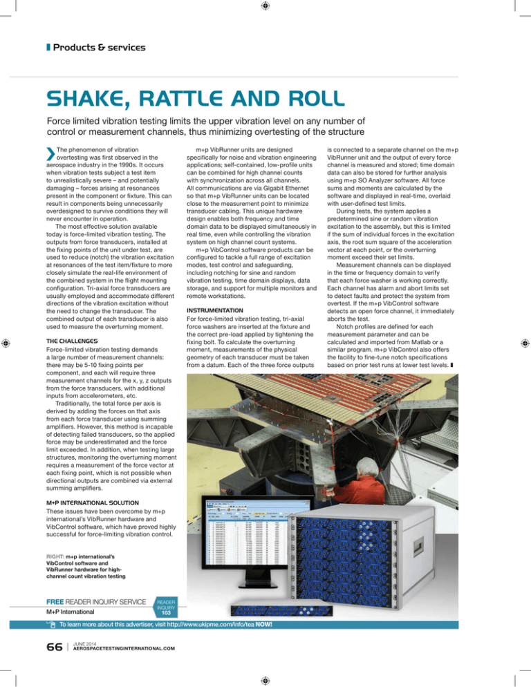
z Products & services shake, rattle and roll Force limited vibration testing limits the upper vibration level on any number of control or measurement channels, thus minimizing overtesting of the structure The phenomenon of vibration overtesting was first observed in the aerospace industry in the 1990s. It occurs when vibration tests subject a test item to unrealistically severe – and potentially damaging – forces arising at resonances present in the component or fixture. This can result in components being unnecessarily overdesigned to survive conditions they will never encounter in operation. The most effective solution available today is force-limited vibration testing. The outputs from force transducers, installed at the fixing points of the unit under test, are used to reduce (notch) the vibration excitation at resonances of the test item/fixture to more closely simulate the real-life environment of the combined system in the flight mounting configuration. Tri-axial force transducers are usually employed and accommodate different directions of the vibration excitation without the need to change the transducer. The combined output of each transducer is also used to measure the overturning moment. THE CHALLENGES Force-limited vibration testing demands a large number of measurement channels: there may be 5-10 fixing points per component, and each will require three measurement channels for the x, y, z outputs from the force transducers, with additional inputs from accelerometers, etc. Traditionally, the total force per axis is derived by adding the forces on that axis from each force transducer using summing amplifiers. However, this method is incapable of detecting failed transducers, so the applied force may be underestimated and the force limit exceeded. In addition, when testing large structures, monitoring the overturning moment requires a measurement of the force vector at each fixing point, which is not possible when directional outputs are combined via external summing amplifiers. m+p VibRunner units are designed specifically for noise and vibration engineering applications; self-contained, low-profile units can be combined for high channel counts with synchronization across all channels. All communications are via Gigabit Ethernet so that m+p VibRunner units can be located close to the measurement point to minimize transducer cabling. This unique hardware design enables both frequency and time domain data to be displayed simultaneously in real time, even while controlling the vibration system on high channel count systems. m+p VibControl software products can be configured to tackle a full range of excitation modes, test control and safeguarding, including notching for sine and random vibration testing, time domain displays, data storage, and support for multiple monitors and remote workstations. INSTRUMENTATION For force-limited vibration testing, tri-axial force washers are inserted at the fixture and the correct pre-load applied by tightening the fixing bolt. To calculate the overturning moment, measurements of the physical geometry of each transducer must be taken from a datum. Each of the three force outputs M+P INTERNATIONAL SOLUTION These issues have been overcome by m+p international’s VibRunner hardware and VibControl software, which have proved highly successful for force-limiting vibration control. RIGHT: m+p international’s VibControl software and VibRunner hardware for highchannel count vibration testing FREE READER INQUIRY SERVICE M+P International READER INQUIRY 103 To learn more about this advertiser, visit http://www.ukipme.com/info/tea NOW! 66 | JUNE 2014 AEROSPACETESTINGINTERNATIONAL.COM is connected to a separate channel on the m+p VibRunner unit and the output of every force channel is measured and stored; time domain data can also be stored for further analysis using m+p SO Analyzer software. All force sums and moments are calculated by the software and displayed in real-time, overlaid with user-defined test limits. During tests, the system applies a predetermined sine or random vibration excitation to the assembly, but this is limited if the sum of individual forces in the excitation axis, the root sum square of the acceleration vector at each point, or the overturning moment exceed their set limits. Measurement channels can be displayed in the time or frequency domain to verify that each force washer is working correctly. Each channel has alarm and abort limits set to detect faults and protect the system from overtest. If the m+p VibControl software detects an open force channel, it immediately aborts the test. Notch profiles are defined for each measurement parameter and can be calculated and imported from Matlab or a similar program. m+p VibControl also offers the facility to fine-tune notch specifications based on prior test runs at lower test levels. z


