High Current Step-Down Controller Regulates to 0.6V Output from
advertisement
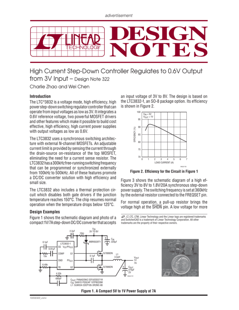
advertisement High Current Step-Down Controller Regulates to 0.6V Output from 3V Input – Design Note 322 Charlie Zhao and Wei Chen The LTC3832 uses a synchronous switching architecture with external N-channel MOSFETs. An adjustable current limit is provided by sensing the current through the drain-source on-resistance of the top MOSFET, eliminating the need for a current sense resistor. The LTC3832 has a 300kHz free-running switching frequency that can be programmed or synchronized externally from 100kHz to 500kHz. All of these features promote a DC/DC converter solution with high efficiency and small size. The LTC3832 also includes a thermal protection circuit which disables both gate drivers if the junction temperature reaches 150°C. The chip resumes normal operation when the temperature drops below 125°C. Design Examples Figure 1 shows the schematic diagram and photo of a compact 1V/7A step-down DC/DC converter that accepts 2.2μF 10Ω 0.01μF LTC3832-1 SS VCC/PVCC2 COMP G1 15k GND MBR0520T1 VIN = 5V VOUT = 1V 95 90 85 80 75 70 0 1 2 3 4 5 LOAD CURRENT (A) Si7806DN Si7806DN 4.32k Figure 3 shows the schematic diagram of a high efficiency 3V to 8V to 1.8V/20A synchronous step-down power supply. The switching frequency is set at 360kHz by the external resistor connected to the FREQSET pin. For normal operation, a pull-up resistor brings the voltage high at the SHDN pin. A low voltage for more L, LT, LTC, LTM, Linear Technology and the Linear logo are registered trademarks and SwitcherCAD is a trademark of Linear Technology Corporation. All other trademarks are the property of their respective owners. L1 3.2μH VOUT 1V 7A + COUT 270μF 2V DN322 F01 680pF COUT: PANASONIC EEFUEOD271R CIN: SANYO POSCAP 10TPB220M L1: SUMIDA CDEP105-3R2MC-88 Figure 1. A Compact 5V to 1V Power Supply at 7A 10/03/322_conv 7 Figure 2. Efficiency for the Circuit in Figure 1 PVCC1 G2 6 DN322 F02 CIN 220μF 0.1μF 6.49k FB 100 VIN 3V TO 8V + 0.1μF an input voltage of 3V to 8V. The design is based on the LTC3832-1, an SO-8 package option. Its efficiency is shown in Figure 2. EFFICIENCY (%) Introduction The LTC ®3832 is a voltage mode, high efficiency, high power step-down switching regulator controller that can operate from input voltages as low as 3V. It integrates a 0.6V reference voltage, two powerful MOSFET drivers and other features which make it possible to build cost effective, high efficiency, high current power supplies with output voltages as low as 0.6V. + D3 MBR0520LT1 DZ MMSZ5242B + 1μF 10Ω + PVCC1 PVCC2 VCC 2.2μF CSS 0.01μF 1k 130k D1 B320A Q2 G2 + PGND COMP RC 18.2k CC 3000pF LO 0.6μH 1k LTC3832 IFB SHDN C1 150pF Q1 IMAX FREQSET RUN 0.1μF G1 SS CIN 220μF 10μF 0.1μF RQ 12k VIN 3V TO 8V COUT 180μF w2 VOUT 1.8V 20A RA 6.04k 1% 470pF GND SENSE + SENSE – NC FB RB 3.01k 1% Q1, Q2: SILICONIX Si7892DP w2 CIN: SANYO POSCAP 10TPB220M COUT: PANASONIC EEFUD0D181R LO: TOKO FDH1055 DN322 F03 NC Figure 3. High Efficiency 3.3V to 1.8V at 20A Synchronous Step-Down DC/DC Converter The LTC3832 also includes a soft-start circuit. The soft-start voltage ramp rate in this circuit is set by CSS. Figure 4 shows the efficiency curve of the circuit. Up to 90% efficiency is obtained with a 3.3V input. For other output voltages, simply change the value of R A. The output voltage can be as low as 0.6V (see Table 1). For higher output currents, parallel more MOSFETs and use a higher current inductor. Table 1. RA Values for Different Output Voltages VOUT (V) RA (Ω) 0.6 0 1.0 2.00k 1.2 3.01k 1.5 4.53k 1.8 6.04k 2.5 9.53k Data Sheet Download www.linear.com Linear Technology Corporation 100 VIN = 3.3V VOUT = 1.8V 95 EFFICIENCY (%) than 100μs at SHDN pin pulls the COMP and SS pins to ground and shuts Q1 and Q2 off. The current limit function is provided by connecting an external resistor RQ from the IMAX pin to the drain of the top MOSFET (Q1). The current limit threshold can be adjusted by the value of RQ based on the RDS(ON) of Q1 and the load requirement. The 0.1μF decoupling capacitor across RQ filters the switching noise. 90 85 80 75 70 0 4 8 12 LOAD CURRENT (A) 16 20 DN322 F04 Figure 4. Efficiency for the Circuit in Figure 3 with VIN = 3.3V Conclusion The LTC3832 is a voltage mode controller optimized for high power, low voltage—as low as 0.6V—applications. It provides a set of features that promote high efficiency while keeping solution costs low. LTC3832 designs may be simulated with SwitcherCAD™ III which can be downloaded from www.linear.com. For applications help, call (408) 432-1900 dn322f_conv LT/TP 1003 316.5K • PRINTED IN THE USA 1630 McCarthy Blvd., Milpitas, CA 95035-7417 (408) 432-1900 ● FAX: (408) 434-0507 ● www.linear.com © LINEAR TECHNOLOGY CORPORATION 2003
