Toroid Design
advertisement

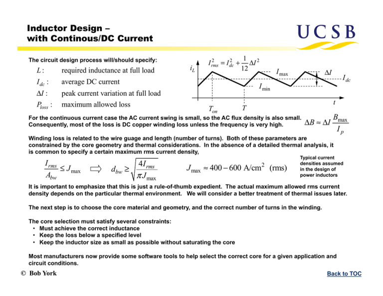
Inductor Design – with Continous/DC Current The circuit design process will/should specify: L: required inductance at full load I dc : average DC current ΔI : peak current variation at full load Ploss : maximum allowed loss iL 2 2 I rms = I dc + 1 2 ΔI 12 I max ΔI I dc I min Ton t T For the continuous current case the AC current swing is small, so the AC flux density is also small. Consequently, most of the loss is DC copper winding loss unless the frequency is very high. ΔB ≈ ΔI Bmax Ip Winding loss is related to the wire guage and length (number of turns). Both of these parameters are constrained by the core geometry and thermal considerations. In the absence of a detailed thermal analysis, it is common to specify a certain maximum rms current density, I rms ≤ J max Abw 4I rms dbw ≥ π J max J max ≈ 400 − 600 A/cm2 (rms) Typical current densities assumed in the design of power inductors It is important to emphasize that this is just a rule-of-thumb expedient. The actual maximum allowed rms current density depends on the particular thermal environment. We will consider a better treatment of thermal issues later. The next step is to choose the core material and geometry, and the correct number of turns in the winding. The core selection must satisfy several constraints: • Must achieve the correct inductance • Keep the loss below a specified level • Keep the inductor size as small as possible without saturating the core Most manufacturers now provide some software tools to help select the correct core for a given application and circuit conditions. © Bob York Back to TOC Typical Core Geometries Some Basic Core shapes C or U core Pot core Toroid E-core There are many variants on the above, here are a few examples PQ EQ RM EP ETD © Bob York Back to TOC Core Comparison Magnetics Inc. Magnetic Cores for Switching Power Supplies , www.mag-inc.com © Bob York Back to TOC Single-Layer Toroid The inductance is given by: b A L = µe N 2 e = N 2 AL le w a To keep the flux density below some specified maximum, the peak current must satisfy: I max ≤ w=b−a h I.D. NBmax Ae L O.D. φ The number of turns that will fit on the toroid is constrained by the inner diameter and wire size: a ? dw θ = 2π − φ : θ = 2π = θ 2( a − d w )sin > dw 2N 2N The copper loss is given by: For a single-layer winding: PCu = ρCu N ( MLT ) 2 I rms Abw Nd w ≤ 2π a dw dbw MLT = 2(h + d w ) + 2( w + d w ) (Note: DC resistance is justified in the continuous current case where the AC current variation is small) The core loss can be estimated from the Steinmetz equation: Pcore = kcore f n ΔB mVe © Bob York ΔB ≈ Δ I Bmax I max Abw = winding angle π 2 dbw 4 dbw : bare wire diameter Abw : bare wire area dw : diameter with insulation Back to TOC Single-Layer Toroid: Core Selection Note that the first two constraints on the previous page scale in opposite ways with the number of turns Ae ≥ LI max NBmax I.D. ≥ Nd w π The product of these two numbers gives The R.H.S can be computed from the circuit specifications and an estimate of the peak flux density, which can be obtained from manufacturer data on specific core materials LI d Ae × I.D. ≥ max w π Bmax This gives simple guidance for choosing the correct core dimensions: we must use a toroid with an area-diameter product that satisfies the above constraint. Once the core is selected, all the geometrical parameters will be known, so we just need to calculate the number of turns: N= Often the manufacturers will provide several choices for AL for a given core dimension. The remaining constraint on copper loss can help us choose: L AL AL > ρCu ( MLT ) PCu Abw L 2 I rms This is a simple method for core selection that closely parallels the area-product method to be developed later © Bob York Back to TOC Note that toroid dimensions are not entirely independent: the inner diameter must scale with the outer diameter, and the height is also constrained. Let s parameterize the core dimensions as follows: ξ≡ I.D. O.D. γ≡ h w I.D./O/D. There are often many possible core sizes and materials that can be selected for a given design. Is there a best design? Catalog cores (chart at right): γ ≈1− 2 ξ ≈ 0.5 − 0.6 0.8 8 0.7 7 0.6 6 0.5 0.4 I.D./O.D. Micrometals h/w: Ferroxcube 0.3 k1 4 3 h/w: Micrometals 0.2 2 0.1 1 0.0 1 With these definitions the various geometrical parameters can all be expressed in terms of the outer radius b: (1! " ) 2 b 2 ! e a = ξ b h = γ (1 − ξ )b Ae = !! #"# $ 5 I.D./O.D. Ferroxcube 10 ! 2! ab = 2! " b "#$ 0 1000 100 O.D. [mm] Aspect Ratio h/w Single-Layer Toroid: A Closer Look at Core Selection MLT ! 2(! +1)(1! ! ) b !# #"## $ k3 k2 Eliminating the number of turns from the equations on the previous page gives these three constraints that relate permeability to core size: 2 ⎛B ⎞ kk µe ≤ ⎜ max ⎟ 1 2 b3 ⎝ I max ⎠ L To limit the peak flux density © Bob York 2 k2 k32 L ⎛ ρCu I rms µe ≥ ⎜ k1 ⎜⎝ Abw PCu 2 ⎞ ⎟⎟ b ⎠ To keep the Ohmic loss below PCu 2 k L⎛ d ⎞ 1 µe ≥ 2 ⎜ w ⎟ 3 k1 ⎝ θ ξ ⎠ b To insure that the required number of turns will fit the core size Back to TOC Example Calculations Circuit Spec: Assumptions: L = 500 µ H I dc = 2 A ξ = 0.5 γ =2 ΔI = 0.4 A Bmax = 0.3T J max = 400 A/cm 2 The shaded region is the range of allowed permeability and core sizes that will satisfy the constraints on number of turns and Bmax. 10000 Required ue (relative) at full load The three constraints are plotted at right for a particular design example: PCu < Pcrit 1000 µe,crit 10 B<Bmax PCu=Pcrit N turns just fit I.D. 1 0 The minimum possible core size and associated permeability and copper loss can be found as: 1/3 bmin ⎛ LI d ⎞ = ⎜ max w ⎟ ⎝ k1Bmax 2πξ ⎠ µe,crit B d = k2 max w I p 2πξ PCu > Pcrit 100 Pcrit 2bmin 50 100 O.D. [mm] ⎛ LI ⎞ = k3 ⎜ max ⎟ ⎝ k1Bmax ⎠ 2/3 This approach gives a quick estimate of the core outer diamater that is required (2 bmin). This is useful because most manufacturers list or label toroids in terms of the O.D. Key tradeoff: reducing ohmic loss requires a larger core size and higher permeability © Bob York 150 1/3 ⎛ 2πξ ⎞ ⎜ ⎟ ⎝ dw ⎠ 2 ⎛ ρCu I rms ⎜⎜ ⎝ Abw ⎞ ⎟⎟ ⎠ Pcrit is the winding loss that would be incurred if the minimum core size is used Back to TOC Single-Layer Toroid: Optimization The parameterization allows us to explore the possibility of optimal toroid geometries: 1 2 ⎤ −1/3 Core has minimum ⎡ bmin ∝ ⎣γ (1 − ξ ) ξ ⎦ ξ = γ = large as possible outer radius when: 3 1/3 ⎛ γ +1⎞⎛ ξ ⎞ PCu ∝ 2 ⎜ 2/3 ⎟ ⎜ ⎟ 1 − ξ γ ⎝ ⎠ ⎝ ⎠ ξ = small as possible Winding loss minimized when: 1 ξ= 3 This suggest a possible design goal of: γ =2 (Charts show that there are a range of values around these design goals that should yield god results) γ =2 But these are not the only possible considerations. For example the designer might want to minimize the footprint on a PC board. For a vertical toroid the device consumes an area of about 2hb, and this is minimized when 1/3 ⎛ ⎞ γ APCB ∝ 2hb = 2 ⎜ 2 ⎟ ξ (1 − ξ ) ⎝ ⎠ ξ= 2 3 γ = small as possible Or we could look for a compromise by minimizing the area-loss product: 1/3 ⎞ ⎛ γ +1⎞⎛ 1 APCB PCu ∝ ⎜ 1/3 ⎟ ⎜ 2 ⎟ γ (1 − ξ ) ξ⎠ ⎝ ⎠⎝ ξ= 1 3 γ= 1 2 Cost is another important factor. Assuming cost is proportional to the volume of ferrite material in the core, the cost-loss product varies as: 1/3 ⎛ ⎞ ⎛ ⎞⎛ ⎞ γ + 1 1 + ξ ξ Cost × PCu ∝ 2 ⎜ 2/3 ⎟ ⎜ Cost ∝ Vcore = π h b2 − a 2 ⎟⎜ ⎟ ( ) ⎝γ ⎠ ⎝ ξ ⎠⎝ 1 − ξ ⎠ ξ = 0.5 γ =2 Catalog data shows that available core geometries are mostly clustered near this latter design goal, but there often other cores available for which the above considerations can help make a judicious choice © Bob York Back to TOC Permability and Material Selection Once a specific core geometry is chosen the design equations should be recalculated as needed, and this will give a range of permeabilities required for the design. Once the desired permeability is known, the core material can be chosen. Powder cores are available in many different mixtures. Alternative a gapped ferrite core could be used. Shown below are representative curves for available mixtures of Ferroxcube MPP material. 80% Note that the effective permeability falls off at high currents. The design calls for a certain permeability at full-load conditions. This means that the chosen material should have a low-field permeability that is significantly higher, to insure the correct inductance at full-load. It is common to choose the material such that the inductance has fallen to no less than 60-70% of its initial low-field value at full-load conditions. © Bob York Back to TOC Core Loss As mentioned, the core loss is typically small for inductors with small AC current variations and low switchign speeds, but this should be checked at the end of the design. Coefficients in the Steinmetz equation can be estimated from manufacturers data. Note that high-mu materials are typically more lossy than low-mu materials 300µ 14µ Losses are related to frequency and the peak AC field, and can be read directly from these charts, where the peak AC field is B ΔB Bˆ = ≈ ΔI max 2 Ip Note that these charts assume sinusoidal variations. Typical switching waveforms are nonsinusoidal, so a more precise analysis should examine the influence of harmonics. © Bob York Back to TOC


