Thermal Equivalent Model of IGBT Modules
I.
Purpose
In order to ensure a sufficient life time of power
electronics application systems, proper thermal
design is indispensable and one of the critical items
to be considered. The thermal equivalent model of
power semiconductors, including IGBTs, is generally
utilized for the design. In this document, selecting
IGBT modules as a representative example is
presented. Thereafter a modelling process is
reviewed.
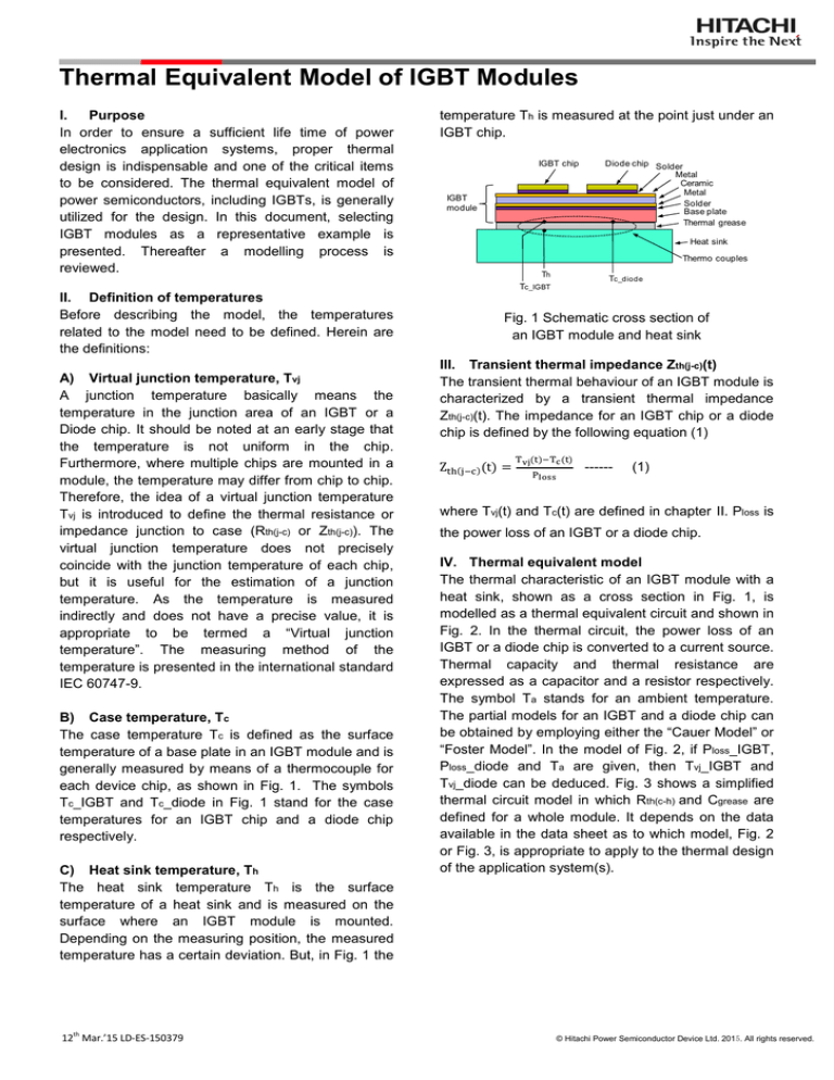
temperature Th is measured at the point just under an
IGBT chip.
IGBT chip
IGBT
module
Diode chip Solder
Metal
Ceramic
Metal
Solder
Base plate
Thermal grease
Heat sink
Thermo couples
Th
Tc_diode
Tc_IGBT
II. Definition of temperatures
Before describing the model, the temperatures
related to the model need to be defined. Herein are
the definitions:
A) Virtual junction temperature, Tvj
A junction temperature basically means the
temperature in the junction area of an IGBT or a
Diode chip. It should be noted at an early stage that
the temperature is not uniform in the chip.
Furthermore, where multiple chips are mounted in a
module, the temperature may differ from chip to chip.
Therefore, the idea of a virtual junction temperature
Tvj is introduced to define the thermal resistance or
impedance junction to case (Rth(j-c) or Zth(j-c)). The
virtual junction temperature does not precisely
coincide with the junction temperature of each chip,
but it is useful for the estimation of a junction
temperature. As the temperature is measured
indirectly and does not have a precise value, it is
appropriate to be termed a “Virtual junction
temperature”. The measuring method of the
temperature is presented in the international standard
IEC 60747-9.
B) Case temperature, Tc
The case temperature Tc is defined as the surface
temperature of a base plate in an IGBT module and is
generally measured by means of a thermocouple for
each device chip, as shown in Fig. 1. The symbols
Tc_IGBT and Tc_diode in Fig. 1 stand for the case
temperatures for an IGBT chip and a diode chip
respectively.
C) Heat sink temperature, Th
The heat sink temperature Th is the surface
temperature of a heat sink and is measured on the
surface where an IGBT module is mounted.
Depending on the measuring position, the measured
temperature has a certain deviation. But, in Fig. 1 the
12th Mar.’15 LD-ES-150379
Fig. 1 Schematic cross section of
an IGBT module and heat sink
III. Transient thermal impedance Zth(j-c)(t)
The transient thermal behaviour of an IGBT module is
characterized by a transient thermal impedance
Zth(j-c)(t). The impedance for an IGBT chip or a diode
chip is defined by the following equation (1)
------
(1)
where Tvj(t) and Tc(t) are defined in chapter Ⅱ. Ploss is
the power loss of an IGBT or a diode chip.
IV. Thermal equivalent model
The thermal characteristic of an IGBT module with a
heat sink, shown as a cross section in Fig. 1, is
modelled as a thermal equivalent circuit and shown in
Fig. 2. In the thermal circuit, the power loss of an
IGBT or a diode chip is converted to a current source.
Thermal capacity and thermal resistance are
expressed as a capacitor and a resistor respectively.
The symbol Ta stands for an ambient temperature.
The partial models for an IGBT and a diode chip can
be obtained by employing either the “Cauer Model” or
“Foster Model”. In the model of Fig. 2, if Ploss_IGBT,
Ploss_diode and Ta are given, then Tvj_IGBT and
Tvj_diode can be deduced. Fig. 3 shows a simplified
thermal circuit model in which Rth(c-h) and Cgrease are
defined for a whole module. It depends on the data
available in the data sheet as to which model, Fig. 2
or Fig. 3, is appropriate to apply to the thermal design
of the application system(s).
© Hitachi Power Semiconductor Device Ltd. 2015. All rights reserved.
Tvj_IGBT
Partial model
for IGBT chip
Cgrease_IGBT
Ploss_IGBT
Tvj_diode
without detailed information about the material
characteristics of the individual layers in an IGBT
module. The thermal impedance of the model is
derived from the circuit of Fig. 5. The equation of the
thermal impedance Zth(j-c)(t) is as follows.
Tc_IGBT Rth(c-h)_IGBT
Rth(h-a)
Th
Partial model
for diode chip
Tc_diode
Csink
Rth(c-h)_diode
------
Ta
Cgrease_diode
Ploss_diode
Fig. 2 Thermal circuit model of the IGBT module
(2)
where τi = Ri ×Ci. This model is realized by tuning
the model’s characteristics to the transient thermal
impedance described in a data sheet.
Foster Model
Tvj_IGBT
Partial model
for IGBT chip
Tvj
Tc
Rth(c-h)
Cgrease
Tvj_diode
Ploss
Th Rth(h-a)
R2
R3
Rn
C1
C2
C3
Cn
Tc
Fig. 5 Foster Model
Csink
Partial model
for diode chip
Ta
V. Modeling process of the Foster Model
In this chapter, the modelling process of the Foster
Model is reviewed using the IGBT type
MBN1200E33E as a working example. Fig. 6 shows
the transient thermal impedance of the module.
Ploss_diode
Fig. 3 Simplified thermal circuit model
A) Cauer Model
Fig. 4 shows the Cauer Model for the IGBT module of
Fig. 1. Employing the Cauer Model, the thermal
behaviour of an IGBT module can be understood.
This model is effective to get a physical image of the
internal behaviour for an IGBT module. Please note
that in order to realize the model, it is necessary to
acquire the material properties of each layer inside
and the module construction. It is therefore not
always practical for IGBT users to employ this model
in designing application systems because it can be
difficult for the users to ascertain the detailed
information needed to realize the model.
Transient thermal impedance Zth(j-c) [K/W]
Ploss_IGBT
R1
0.1
Diode
0.01
IGBT
0.001
0.0001
0.001
0.01
0.1
1
10
Time t [s]
Fig. 6 Zth(j-c) of an IGBT module MBN1200E33E
Cauer Model
Tvj
Ploss
Rchip
Cchip
Rsolder
Csolder
Rmetal
Cmetal
Rceramic
Cceramic
Rmetal
Cmetal
Rsolder
Csolder
Rbase
Cbase
Tc
Rth(c-h) Th
Cgrease
Rth(h-a)
Csink
Ta
Fig. 4 Cauer Model
B) Foster Model
The Foster Model, Fig. 5, consists of series
connected RC elements, where each element is the
parallel circuit of a resistor and a capacitor. In
contrast to the Cauer Model, the element does not
have any physical significance, but the model is an
effective tool to design application systems, because
in contrast to the Cauer Model, it can be realized
12th Mar.’15 LD-ES-150379
The Foster Model is tuned to the impedance curve of
Fig. 6. The greater the number of terms in equation
(2) is, the more accurate the tuning of the model will
become. However, if the number of the terms is too
large, the tuning becomes complicated because of
the large number of parameters to be tuned. On the
other hand, in order to keep the practical accuracy of
the model’s characteristics, the number of the terms
should ideally be more than or equal to 4. For the
algorithmic tuning, there are various methods
possible. The least-squares method is generally
employed. Fig. 7 shows the tuned results for IGBT
chips. Lines i = 1, 2, 3, and 4 show the impedance
characteristics of four terms in Zth(j-c)(t). Fig. 8 shows
© Hitachi Power Semiconductor Device Ltd. 2015. All rights reserved.
the tuned results for diode chips. The tuned data is
input into Table 1.
1.00E-02
Zth(J-C)
i= 1
i= 2
i= 3
Terms
Transient thermal impedance [K/W]
1.00E-01
The life time model predicts the life time of an IGBT
module based on the fluctuation of Tc_IGBT,
Tc_diode, Tvj_IGBT and Tvj_diode. The consideration
flow shown in Fig. 9 can be applied to realize a life
time simulator of power electronic application
systems using general purpose simulation tools.
1.00E-03
Ta
VCE,VAK
Operating
conditions
i= 4
1.00E-04
Ploss_IGBT
Circuit
Model
IC,IA
fSW
Device Loss
Model
Ploss_diode
Thermal
Model
TC_IGBT
TC_diode
Tvj_IGBT
Tvj_diode
Life Time
Model
Life time
1.00E-05
Fig. 9 Consideration flow for life time estimation
1.00E-06
1.00E-06 1.00E-05 1.00E-04 1.00E-03 1.00E-02 1.00E-01 1.00E+001.00E+01
Time t [s]
Fig. 7 Tuned results of Zth(j-c) for IGBT_chips
Zth(J-C)
i= 1
i= 2
i= 3
1.00E-02
Terms
Transient thermal impedance [K/W]
1.00E-01
1.00E-03
i= 4
1.00E-04
1.00E-05
1.00E-06
1.00E-06 1.00E-05 1.00E-04 1.00E-03 1.00E-02 1.00E-01 1.00E+00 1.00E+01
Time t [s]
Fig. 8 Tuned results of Zth(j-c) for diode_chips
Table 1 Tuned data for MBN1200E33E
i
τ [i]
R [i,IGBT]
R [i,Diode]
1
2
3
4
1.51E-01 2.49E-02 3.86E-03 6.61E-04
5.24E-03 1.54E-03 1.57E-03 1.45E-04
1.04E-02 3.19E-03 3.08E-03 2.99E-04
Unit
sec
K/W
K/W
VI. Utilization of the thermal circuit model
The thermal equivalent circuit model is useful in
evaluating the thermal performance of power
electronic application systems. The block diagram in
Fig. 9 shows a general way of considering life time
estimation for a system. The circuit model simulates
the electrical behaviour of the system, such as an
inverter, according to operating conditions and
outputs the values: VCE; VAK; IC; IA; and a switching
frequency, fSW, for the calculation of a power
module’s power loss. The device loss model
calculates the power loss using the aforementioned
input and outputs values, Ploss_IGBT and Ploss_diode.
The thermal model simulates the thermal transient
behaviour of an IGBT module according to
Ploss_IGBT, Ploss_diode and Ta. Tvj_IGBT and
Tvj_diode are then applied to the device loss model.
12th Mar.’15 LD-ES-150379
© Hitachi Power Semiconductor Device Ltd. 2015. All rights reserved.


