Installation Instructions for 5-inch Tachometer
advertisement

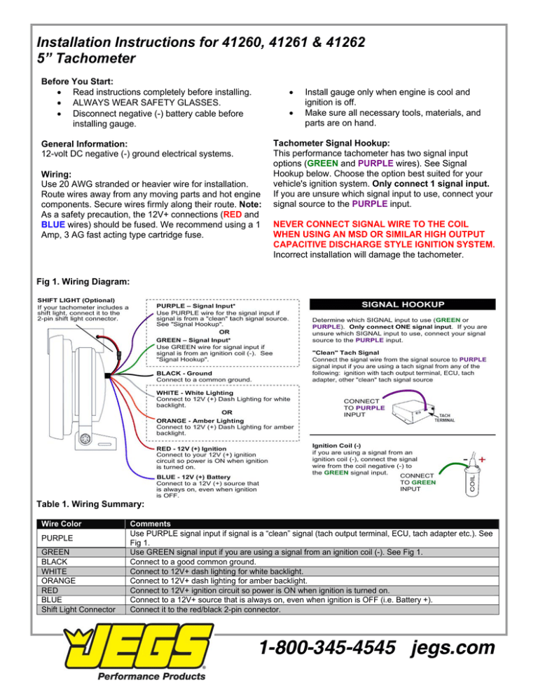
Installation Instructions for 41260, 41261 & 41262 5” Tachometer Before You Start: • Read instructions completely before installing. • ALWAYS WEAR SAFETY GLASSES. • Disconnect negative (-) battery cable before installing gauge. • • General Information: 12-volt DC negative (-) ground electrical systems. Wiring: Use 20 AWG stranded or heavier wire for installation. Route wires away from any moving parts and hot engine components. Secure wires firmly along their route. Note: As a safety precaution, the 12V+ connections (RED and BLUE wires) should be fused. We recommend using a 1 Amp, 3 AG fast acting type cartridge fuse. Install gauge only when engine is cool and ignition is off. Make sure all necessary tools, materials, and parts are on hand. Tachometer Signal Hookup: This performance tachometer has two signal input options (GREEN and PURPLE wires). See Signal Hookup below. Choose the option best suited for your vehicle's ignition system. Only connect 1 signal input. If you are unsure which signal input to use, connect your signal source to the PURPLE input. NEVER CONNECT SIGNAL WIRE TO THE COIL WHEN USING AN MSD OR SIMILAR HIGH OUTPUT CAPACITIVE DISCHARGE STYLE IGNITION SYSTEM. Incorrect installation will damage the tachometer. Fig 1. Wiring Diagram: Table 1. Wiring Summary: Wire Color PURPLE GREEN BLACK WHITE ORANGE RED BLUE Shift Light Connector Comments Use PURPLE signal input if signal is a “clean” signal (tach output terminal, ECU, tach adapter etc.). See Fig 1. Use GREEN signal input if you are using a signal from an ignition coil (-). See Fig 1. Connect to a good common ground. Connect to 12V+ dash lighting for white backlight. Connect to 12V+ dash lighting for amber backlight. Connect to 12V+ ignition circuit so power is ON when ignition is turned on. Connect to a 12V+ source that is always on, even when ignition is OFF (i.e. Battery +). Connect it to the red/black 2-pin connector. 1-800-345-4545 jegs.com View and Clear Peak RPM Value • To view the peak RPM value, press the UP button. The pointer will indicate the previous peak RPM. • To exit, press the UP button again. • To clear the peak RPM, press and hold the DOWN button for 3 seconds while viewing the peak RPM value. The pointer will move to zero to confirm that the peak RPM value has been cleared. PPR (Pulse per Revolution) PPR (pulses per revolution) relates to how many times the ignition fires per crankshaft revolution. Because tachometer outputs on modern vehicles can range from 1 PPR to 4 PPR for a V8 engine the new standard is to refer to PPR. For standard ignitions PPR is typically half the number of cylinders. Shift Light RPM Set Point • Press the MENU button to access SHIFT mode. The pointer will indicate the current shift light activation set point. • To change the shift light activation set point, press the UP or DOWN buttons. Hold the UP or DOWN button for rapid increase or decrease of the set point. • Press MENU to save your changes and exit SHIFT mode. PPR Setting 0.5 PPR (1 Cyl) 1 PPR (2 Cyl) 2 PPR (4 Cyl) 3 PPR (6 Cyl) 4 PPR (8 Cyl) 5 PPR (10 Cyl) 6 PPR (12 Cyl) Pointer Position, RPM 500 1000 2000 3000 4000 5000 6000 Use the UP/DOWN buttons to change the PPR setting. Press MENU to save your changes and exit calibration mode. Through-Dial Lighting Color For white backlight, connect the WHITE wire to your 12V+ dash lighting. For amber backlight, connect the ORANGE wire to your 12V+ dash lighting. Tachometer Signal Hookup (Additional Info) This performance tachometer has two signal input options. Choose the option best suited for your vehicle's ignition system. Only connect 1 signal input. If you are unsure which signal input to use, connect your signal source to the PURPLE input. Dimmable LED Lighting This gauge features through-dial, high-definition LED lighting that will not dim when used with standard dash dimmers. Lens Cleaning The gauge lens is made of acrylic plastic. Do not use any chemicals or abrasives on the lens. To prevent scratching, caution must be used when cleaning. To clean, wipe lightly with a damp soft cloth. Lens Protective Film The gauge comes with a soft protective plastic film on the lens. Remove the protective film when gauge installation is complete. Calibration To calibrate, hold down the MENU button while turning the ignition on. The pointer will indicate the current PPR setting (0.5-6) as shown in the table below. Purple Wire Input: “Clean” Signal On applications where a "clean" tachometer signal output is available (typically a 12V square wave signal) connect the signal wire from the signal source to the PURPLE wire on the back of the tachometer. Applications with “clean” tachometer output signals include ignition boxes with tachometer output terminal, dedicated tachometer signal from ECU, and tachometer adapters. Green Wire Input: Ignition Coil (-) On standard ignition coils connect the signal wire from the coil negative (-) to the GREEN wire on the back of the tachometer. Note: Some ignition coil applications (including many 4 cylinder applications) output a relatively clean signal. If this is the case for your application you may need to use the PURPLE signal input wire. 1-800-345-4545 jegs.com

