LED23
rev 2.0 29.04.2015
Description
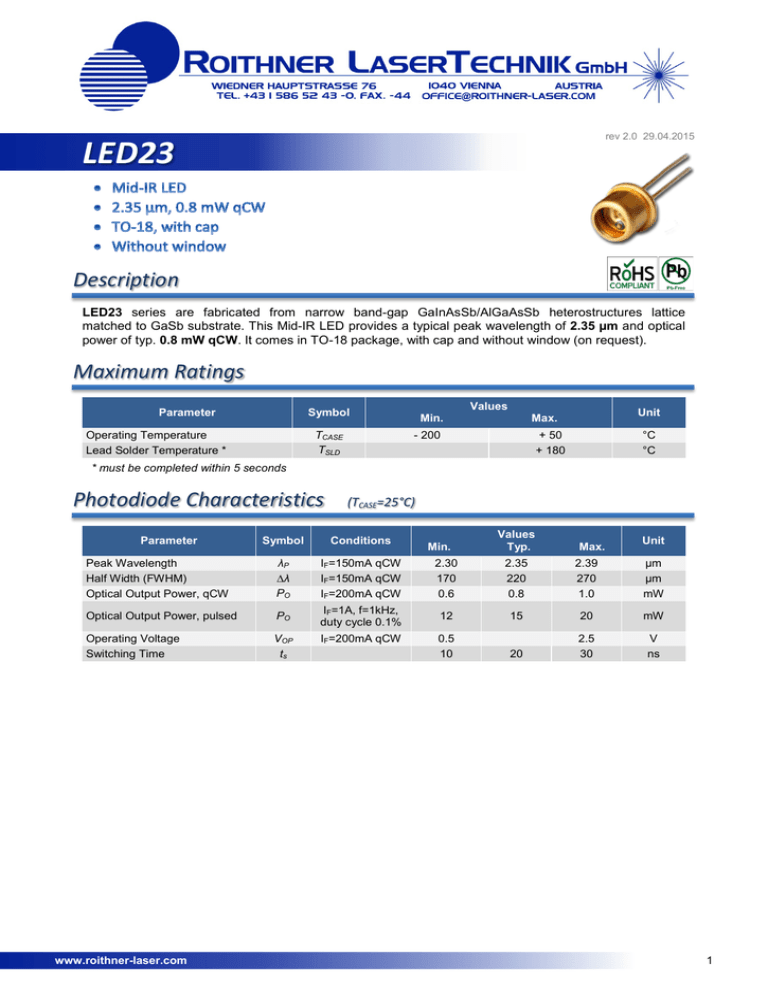
LED23 series are fabricated from narrow band-gap GaInAsSb/AlGaAsSb heterostructures lattice
matched to GaSb substrate. This Mid-IR LED provides a typical peak wavelength of 2.35 µm and optical
power of typ. 0.8 mW qCW. It comes in TO-18 package, with cap and without window (on request).
Maximum Ratings
Parameter
Values
Symbol
TCASE
TSLD
Operating Temperature
Lead Solder Temperature *
Min.
Unit
Max.
- 200
+ 50
+ 180
°C
°C
* must be completed within 5 seconds
Photodiode Characteristics
Parameter
(TCASE=25°C)
Values
Typ.
Symbol
Conditions
Peak Wavelength
Half Width (FWHM)
Optical Output Power, qCW
λP
∆λ
PO
IF=150mA qCW
IF=150mA qCW
IF=200mA qCW
2.30
170
0.6
2.35
220
0.8
2.39
270
1.0
µm
µm
mW
Optical Output Power, pulsed
PO
IF=1A, f=1kHz,
duty cycle 0.1%
12
15
20
mW
Operating Voltage
Switching Time
VOP
ts
0.5
10
20
2.5
30
V
ns
www.roithner-laser.com
IF=200mA qCW
Min.
Max.
Unit
1
Performance Characteristics
Spectra At Different Temperatures
(qCW, IF=150mA)
Intensity [a.u.]
Intensity [a.u.]
Spectra At Different Currents
(qCW, TCASE=25°C)
Wavelength [nm]
Output Power vs. Forward Current
(qCW, TCASE=25°C)
Forward Current vs. Forward Voltage
(TCASE=25°C)
Output Power [µW]
Forward Current [mA]
Wavelength [nm]
Forward Current [mA]
Forward Voltage [V]
Normalized Intensity [a.u.]
Beam Divergence
Angle [°]
www.roithner-laser.com
2
Outline Dimensions
LED23
TO-18, without window
Lead
Description
PIN 1
LD Anode
PIN 2
LD Cathode
Material – kovar, finish – gold/plating
All Dimensions in mm
Operating Regime
LED Basic Circuit Connection
Suitable Drivers And Evaluation Boards
•
D-31M
•
D-41
•
D-51
•
mD-1c
•
mD-1p
We recommend to use Quasi Continuous Wave (qCW) mode with duty cycle 50% or 25% to obtain maximum
average optical power, and short Pulse mode to obtain maximum peak power.
CW (continuous wave) mode is NOT recommended!
Quasi Continuous Wave (qCW) mode
www.roithner-laser.com
Pulse Mode
3
Precautions
Cautions:
• Check your connection circuits before turning on the LED.
• Mind the LED polarity: LED anode is marked with a RED dot.
• DO NOT connect the LED to the multimeter.
Soldering:
•
•
•
•
•
Do avoid overheating of the LED
Do avoid electrostatic discharge (ESD)
Do avoid mechanical stress, shock, and vibration
Do only use non-corrosive flux
Do not apply current to the LED until it has cooled down to room temperature after soldering
Static Electricity:
LEDs are sensitive to electrostatic discharge (ESD). Precautions against ESD must be taken
when handling or operating these LEDs. Surge voltage or electrostatic discharge can result in
complete failure of the device.
Operation:
Do only operate LEDs with a current source.
Running these LEDs from a voltage source will result in complete failure of the device.
Current of a LED is an exponential function of the voltage across it. Usage of current regulated drive
circuits is mandatory.
© All Rights Reserved
The above specifications are for reference purpose only and subjected to change without prior notice
www.roithner-laser.com
4


