The Nyquist Stability Criterion
advertisement
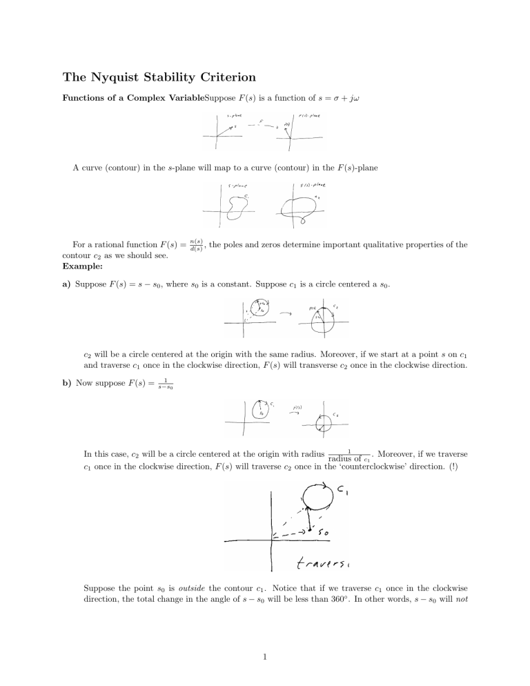
The Nyquist Stability Criterion Functions of a Complex VariableSuppose F (s) is a function of s = σ + jω A curve (contour) in the s-plane will map to a curve (contour) in the F (s)-plane For a rational function F (s) = contour c2 as we should see. Example: n(s) d(s) , the poles and zeros determine important qualitative properties of the a) Suppose F (s) = s − s0 , where s0 is a constant. Suppose c1 is a circle centered a s0 . c2 will be a circle centered at the origin with the same radius. Moreover, if we start at a point s on c1 and traverse c1 once in the clockwise direction, F (s) will transverse c2 once in the clockwise direction. b) Now suppose F (s) = 1 s−s0 1 In this case, c2 will be a circle centered at the origin with radius . Moreover, if we traverse radius of c1 c1 once in the clockwise direction, F (s) will traverse c2 once in the ‘counterclockwise’ direction. (!) Suppose the point s0 is outside the contour c1 . Notice that if we traverse c1 once in the clockwise direction, the total change in the angle of s − s0 will be less than 360◦ . In other words, s − s0 will not 1 make a full rotation about the origin which implies c2 will not encircle or contain the origin. Question: What happens with F (s) = (s − s0 )2 ? We can state a general result known as the Principle of the Argument as follows. Let G(s) be a rational function with poles at p1 , . . . , pn and zeros at z1 , . . . , zn . Let c1 be a closed contour in the s-plane that does not pass through any poles or zeros of G(s). [Note: Some poles and zeros may be inside c1 and some outside c1 .] Then the contour c2 in the G(s)-plane encircles the origin N times in the clockwise direction, where N = Z −P z = # of zeros inside c1 p = # of poles inside c1 Nyquist Criterion We can apply the principle of the argument to determine stability of a closed-loop system based on its open-loop frequency response. 2 y(s)/R(s) = T (s) = KG(s) ; 1 + KG(s) KG(s) = KGc (s) · Gp (s) Note: We can either consider 1 + KG(s) with respect to the origin or KG(s) with respect to the point (−1, 0). We let c1 be a contour that encircles the entire R.H.P. We can now state the Nyquist Principle as follows: Nyquist − − − Suppose KG(s) has no poles or zeros on the jω-axis and let F (ω) = KG(jω) − 60 ≤ ω ≤ ∞ be the frequency response function. Let c2 be the image of F . Let P be the number of unstable poles of G(s) (these are the open-loop unstable poles). Let N be the number of clockwise encirclements of (−1, 0) of the Nyquist plot. Then the number of unstable closed-loop poles is Z = N + P. Proof: Remember that we are looking for zeros of 1 + KG(s). Note that 1 + KG(s) = 1+K d(s) + Kn(s) n+s = d(s) d(s) implies poles of 1 + KG(s) = poles of G(s) zoros of 1 + KG(s) = routes of d(s) + Kn(s) so the contour determined by 1 + KG(s) will encircle the origin N + Z − P times. Example: G(jω) = = 1 (jω + 1)2 1 − ω2 2ω −j (1 + ω 2 )2 (1 + ω 2 )2 3 The gain K scales the magnitude but does not affect the phase. Conclusion: Stable for all K > 0. Example: G(jω) = 1 1 − 3ω 2 jω(3 − ω 2 ) = + 3 2 3 (jω + 1) (1 + ω ) (1 + ω 2 )3 Stable for K < 8. Check with Routh-Hurwitz criterion: The closed-loop characteristic polynomial is (s + 1)3 + K = s3 + 3s2 + 3s + 1 + K implies stable for 3.3 > 1 + K implies K < 8. Poles at the Origin Recall that the contour c1 cannot pass through any poles or zeros. Thus, for open poles and zeros on the jω-axis, the Nyquist approach above does not work, and must be modified. The most common case is when there is a pole at s = 0, i.e., Type number ≥ 1. Example: In this case we modify c1 by going around the pole as shown 4 For ω = 0− , the magnitude of G(jω) is infinite and the phase is ≈ 90◦ 1 − −1 6 = −(−90) − tan ≈ +90. 2 −j ∈ (−j ∈ +1) 1 For ω = 0+ the magnitude is infinite and the phase is ≈ −90. In other words, as ω passes through zero, the nyquist plot goes from +∞ → −∞. Stability Margins In many cases the closed-loop system will be stable for a range of gain 0 < K < Kmax . For a given design, the Gain Margin = factor by which the gain can be raised before instability results Phase Margin = amount that the phase angle can be increased before instability results The vector margin or stability margin is the minimum distance from the Nyquist plot to the point (−1, 0). 5 The vector margin combines gain and phase margins into a single measure. These quantities are useful for design problems. Stability Margins from the Bode Plot (see Section 6.2) The gain and phase margins can often be picked directly off the Bode plots. Recall that the critical point for stability, (−1, 0), corresponds to a magnitude of 1 and phase of ±180. 6
