PedalSync™
Hi-V Pot
Digital
Potentiometer
Module
Key Features
•
Programmable digital replacement for analog potentiometers
•
Extended 18 volt and 5 mA power limits
•
Fits in standard DIP socket
•
Power filter capacitors on module
•
Designed for use with the PedalSync MV-56B Four Pots Module
•
CadSoft Eagle footprint available at www.PedalSync.com
Overview
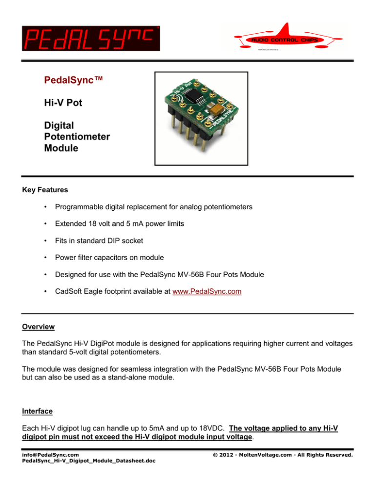
The PedalSync Hi-V DigiPot module is designed for applications requiring higher current and voltages
than standard 5-volt digital potentiometers.
The module was designed for seamless integration with the PedalSync MV-56B Four Pots Module
but can also be used as a stand-alone module.
Interface
Each Hi-V digipot lug can handle up to 5mA and up to 18VDC. The voltage applied to any Hi-V
digipot pin must not exceed the Hi-V digipot module input voltage.
info@PedalSync.com
PedalSync_Hi-V_Digipot_Module_Datasheet.doc
© 2012 - MoltenVoltage.com - All Rights Reserved.
PedalSync™
Hi-V Pot Module
Datasheet - p.2
Table of Hi-V Pot Module v1.0 Pin Assignments
Pin
1
2
3
4
5
6
7
8
9
10
Connection
Chip Select (CS)
Clock (CLK)
Serial Data Input (SDI)
Ground (power)
Positive Voltage (18VDC max)
Positive Voltage (18VDC max)
Circuit Pot Lug 1
Circuit Pot Lug 2 (wiper)
Circuit Pot Lug 3
not connected
The Hi-V Digipot module can be used in place of standard mechanical potentiometer as long as the
voltage and current limits are not exceeded. The minimum input voltage is 4.5VDC.
The Hi-V Digipot module was designed to fit into a standard 10-pin DIP placement. Solder the
header pin strips provided with the module into the holes.
Note: use an 8-pin DIP setup with the PedalSync MV-56B Four Pots module, as described
below
Connect Pin 7 in place of the first lug of the analog potentiometer. Connect Pin 8 in place of the
wiper of the analog potentiometer. Connect Pin 9 in place of the third lug of the analog
potentiometer.
The resistance is divided into 256 separate and equal steps.
Note: Digipots have a nominal amount of resistance in the wiper. As such, the extremes of
resistance are generally about 4% lower than the total resistance.
info@PedalSync.com
PedalSync_Hi-V_Digipot_Module_Datasheet.doc
© 2012 - MoltenVoltage.com - All Rights Reserved.
PedalSync™
Hi-V Pot Module
Datasheet - p.3
Because of the 256-step architecture, “zippering” may be audible when subjecting the digipots to realtime control in sensitive audio applications.
Follow this link to the underlying AD5290 digital potentiometer datasheet for information on data
transfer protocol and more:
http://www.analog.com/static/imported-files/data_sheets/AD5290.pdf
Note: Although the AD5290 can handle even higher voltages, the Hi-V Pot module is limited to
18VDC
Interfacing With The PedalSync MV-56B Four Pots Module
MV-56B sends real-time or programmed resistance data to PedalSync Hi-V Digipot Modules.
The Hi-V Digipot module was designed to fit into a 10-pin DIP socket.
To interface with the MV-56B Four Pots module’s 8-pin DIP pads, cut one pin off the 5-pin header
strips (provided) with wire clippers. Solder the 4-pin header strip in the top 4 pins on each side while
leaving the power connection (pins 5 and 6) empty.
Note: The Hi-V Pot modules fit into 8-pin DIP sockets or can be soldered in place for
applications requiring a lower profile.
The Hi-V digipot module was designed so the input voltage pins can be easily interconnected with a
short bare wire (0.2”) from one module to the next, as seen in the photo, above.
The Power input will then be connected to the external circuit by a jumper wire to one of the open
power input pins (such as the green wire in the lower right of the photo, above).
info@PedalSync.com
PedalSync_Hi-V_Digipot_Module_Datasheet.doc
© 2012 - MoltenVoltage.com - All Rights Reserved.
PedalSync™
Hi-V Pot Module
Datasheet - p.4
Generating A Programmed Voltage
An op amp interface can output a programmed voltage. The following Microchip application notes
give a number of examples for creating programmable amplifiers using digital potentiometers:
Optimizing the Digital Potentiometer in Precision Circuits - AN691
http://ww1.microchip.com/downloads/en/AppNotes/00691a.pdf
Using Digital Potentiometers for Programmable Amplifier Gain - AN1316
http://ww1.microchip.com/downloads/en/AppNotes/01316A.pdf
Noise
Always use filtered and regulated power with the PedalSync Hi-V Pot module.
Follow proper PCB layout design rules and isolate the digital and analog sections of your circuit as
much as possible.
Related Products
•
Use with PedalSync Four Pots chip MV-56B and module to store and recall 4 potentiometer
settings.
Currently only 100K Hi-V DigiPot modules are available but 10K and 50K are coming soon.
Support
info@PedalSync.com
DISCLAIMER
Information contained in this publication regarding device applications and the like is provided only for
your convenience and may be superseded by updates. It is your responsibility to ensure that your
application meets with your specifications. MOLTEN VOLTAGE MAKES NO REPRESENTATIONS
OR WARRANTIES OF ANY KIND WHETHER EXPRESS OR IMPLIED, WRITTEN OR ORAL,
STATUTORY OR OTHERWISE, RELATED TO THE INFORMATION, INCLUDING BUT NOT
LIMITED TO ITS CONDITION, QUALITY, PERFORMANCE, MERCHANTABILITY OR FITNESS
FOR PURPOSE. Molten Voltage disclaims all liability arising from this information and its use. No
licenses are conveyed, implicitly or otherwise, under any Molten Voltage intellectual property rights.
PedalSync, Tru-Foot, Molten Voltage, Visionary Effects, “Design simple Design sublime”, and “the future just showed up”
are all trademarks of Molten Voltage. Legal@MoltenVoltage.com
info@PedalSync.com
PedalSync_Hi-V_Digipot_Module_Datasheet.doc
© 2012 - MoltenVoltage.com - All Rights Reserved.


