P (707) 525-9941
F (707) 575-7046
EMGPICKUPS.COM
SOLID SHAFT
SPLIT SHAFT
INSTALLATION INFORMATION
EMG MODEL: B124 TONE CONTROL
(ACTIVE PICKUP INPUT 25K OHM, BLACK PC BOARD)
(PASSIVE PICKUP INPUT 500K OHM, GREEN PC BOARD)
General Operation
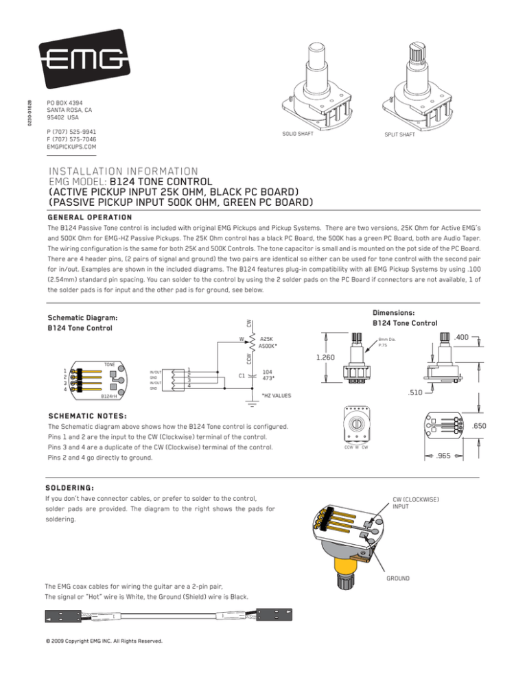
The B124 Passive Tone control is included with original EMG Pickups and Pickup Systems. There are two versions, 25K Ohm for Active EMG’s
and 500K Ohm for EMG-HZ Passive Pickups. The 25K Ohm control has a black PC Board, the 500K has a green PC Board, both are Audio Taper.
The wiring configuration is the same for both 25K and 500K Controls. The tone capacitor is small and is mounted on the pot side of the PC Board.
There are 4 header pins, (2 pairs of signal and ground) the two pairs are identical so either can be used for tone control with the second pair
for in/out. Examples are shown in the included diagrams. The B124 features plug-in compatibility with all EMG Pickup Systems by using .100
(2.54mm) standard pin spacing. You can solder to the control by using the 2 solder pads on the PC Board if connectors are not available, 1 of
the solder pads is for input and the other pad is for ground, see below.
A25K
A500K*
W
TONE
1
2
3
4
Dimensions:
B124 Tone Control
CW
Schematic Diagram:
B124 Tone Control
CCW
0230-0162B
PO BOX 4394
SANTA ROSA, CA
95402 USA
IN/OUT
GND
IN/OUT
GND
1
2
3
4
C1
B124rH
.400
8mm Dia.
P.75
1.260
104
473*
.510
*HZ VALUES
SCHEMATIC NOTES:
The Schematic diagram above shows how the B124 Tone control is configured.
Pins 1 and 2 are the input to the CW (Clockwise) terminal of the control.
Pins 3 and 4 are a duplicate of the CW (Clockwise) terminal of the control.
Pins 2 and 4 go directly to ground.
.650
CCW W CW
.965
SOLDERING:
If you don’t have connector cables, or prefer to solder to the control,
solder pads are provided. The diagram to the right shows the pads for
soldering.
CW (CLOCKWISE)
INPUT
GROUND
The EMG coax cables for wiring the guitar are a 2-pin pair,
The signal or “Hot” wire is White, the Ground (Shield) wire is Black.
© 2009 Copyright EMG INC. All Rights Reserved.
Diagram NOTES:
Pairs 1-2 and 3-4 are interchangeable, both are the CW pair.
Passive tone controls like the B124 are wired parallel to the signal of the pickup, or at the output of the instrument. There is only an “input”, not an
output of a passive tone control. The B124 has two additional header pins (3-4) that could be called “signal-thru” or “pass-thru” so that if the
instrument is wired with a master tone control, the signal to the output jack can be gotten from the tone control. This is most useful if the instrument
is wired Volume/Volume/Master Tone and does not have a selection switch. The diagrams below will further explain.
Diagram #1
Tone control input on either pair 1-2 or 3-4
“Signal-thru” to output jack on either pair 1-2 or 3-4
6
5
4
3
2
1
FROM PICKUP
TONE
1
2
3
4
VOLUME
TO OUTPUT JACK
B124rH
PASSIVE
TONE
Independent volume with 2 pickups and no selection switch:
Diagram #2 illustrates another example of the benefit of the second set of pins on the tone control, it shows a similar wiring arrangement as above
but in an instrument with two pickups and no selection switch. This is similar to a Fender Jazz Bass*.
Diagram #2
NECK PICKUP
BRIDGE
VOLUME
NECK
VOLUME
TONE
6
5
4
3
2
1
BRIDGE PICKUP
PASSIVE
TONE
1
2
3
4
TO OUTPUT JACK
Independent Volume with 2 pickups and a selection switch:
Diagram #3 shows a very typical tone control wiring for a Les Paul style guiar, two pickups with a selection switch. As you can see, the tone controls
have a coax cable going to pins 1-2 (or 3-4). This illustrates that there is only an “input” needed to the tone control, and in this instance the signal is
not being “passed-thru”.
Diagram #3
COAX CABLES
TO B157 PICKUP BUSS
B124rH
4
3
2
1
FROM NECK PICKUP
TONE
NECK VOLUME
NECK TONE
B124rH
4
3
2
1
FROM BRIDGE PICKUP
TONE
BRIDGE VOLUME
B124 Page 2
*Fender Jazz Bass is a registered trademark of FMIC.
BRIDGE TONE

