w
Inductance Loop Vehicle Detector Function – Setting and Adjustments
Loop Module Settings:
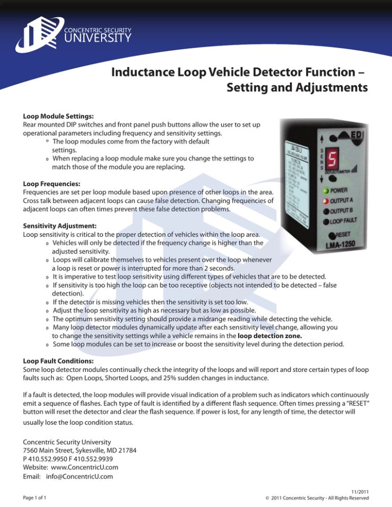
Rear mounted DIP switches and front panel push buttons allow the user to set up
operational parameters including frequency and sensitivity settings.
o The loop modules come from the factory with default
settings.
0 When replacing a loop module make sure you change the settings to match those of the module you are replacing.
Loop Frequencies:
Frequencies are set per loop module based upon presence of other loops in the area.
Cross talk between adjacent loops can cause false detection. Changing frequencies of
adjacent loops can often times prevent these false detection problems.
Sensitivity Adjustment:
Loop sensitivity is critical to the proper detection of vehicles within the loop area.
0 Vehicles will only be detected if the frequency change is higher than the adjusted sensitivity.
0 Loops will calibrate themselves to vehicles present over the loop whenever a loop is reset or power is interrupted for more than 2 seconds.
0 It is imperative to test loop sensitivity using different types of vehicles that are to be detected.
0 If sensitivity is too high the loop can be too receptive (objects not intended to be detected – false detection).
0 If the detector is missing vehicles then the sensitivity is set too low.
0 Adjust the loop sensitivity as high as necessary but as low as possible.
0 The optimum sensitivity setting should provide a midrange reading while detecting the vehicle.
0 Many loop detector modules dynamically update after each sensitivity level change, allowing you to change the sensitivity settings while a vehicle remains in the loop detection zone.
0 Some loop modules can be set to increase or boost the sensitivity level during the detection period.
Loop Fault Conditions:
Some loop detector modules continually check the integrity of the loops and will report and store certain types of loop
faults such as: Open Loops, Shorted Loops, and 25% sudden changes in inductance.
If a fault is detected, the loop modules will provide visual indication of a problem such as indicators which continuously
emit a sequence of flashes. Each type of fault is identified by a different flash sequence. Often times pressing a “RESET”
button will reset the detector and clear the flash sequence. If power is lost, for any length of time, the detector will
usually lose the loop condition status.
Concentric Security University
7560 Main Street, Sykesville, MD 21784
P 410.552.9950 F 410.552.9939
Website: www.ConcentricU.com
Email: info@ConcentricU.com
Page 1 of 1
11/2011
© 2011 Concentric Security - All Rights Reserved
