Ferrite Bead Laboratory
Copyright (C) 2001, 2006 Robert J. Weber. All rights reserved.
Modified August 18, 2006
Purpose: Determine the equivalent circuit of a ferrite bead. The microwave
engineer uses a ferrite bead to pass direct current (dc) to a circuit while at the
same time the ferrite bead provides a measure of isolation between the bias supply
and the circuit. The loss (high frequency resistance) of the ferrite bead
minimizes the risk of parasitic resonances between several reactive components that
exist in the circuit to be biased and the bias supply. Other applications include
providing a high permeability low loss core for transformer or inductor
applications.
Calculating the Approximate Inductance of a Ferrite Bead
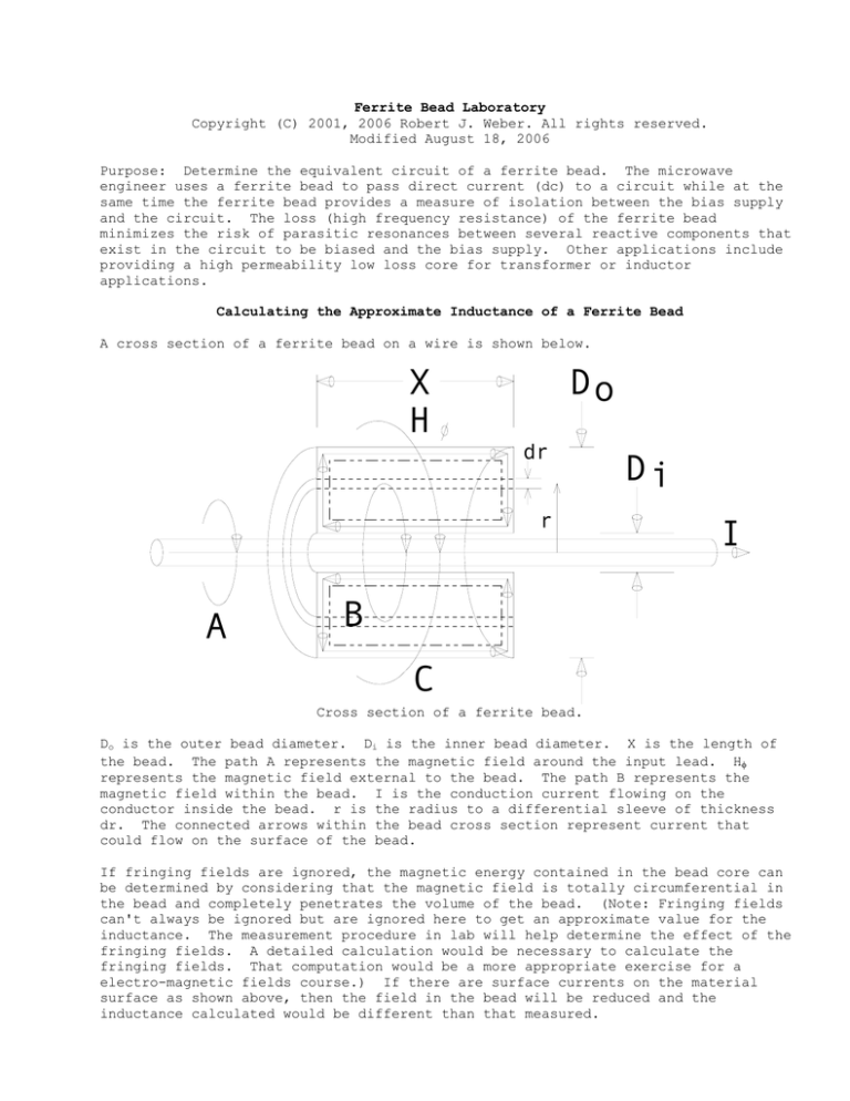
A cross section of a ferrite bead on a wire is shown below.
X
H
Do
dr
r
A
Di
I
B
C
Cross section of a ferrite bead.
Do is the outer bead diameter. Di is the inner bead diameter. X is the length of
the bead. The path A represents the magnetic field around the input lead. Hφ
represents the magnetic field external to the bead. The path B represents the
magnetic field within the bead. I is the conduction current flowing on the
conductor inside the bead. r is the radius to a differential sleeve of thickness
dr. The connected arrows within the bead cross section represent current that
could flow on the surface of the bead.
If fringing fields are ignored, the magnetic energy contained in the bead core can
be determined by considering that the magnetic field is totally circumferential in
the bead and completely penetrates the volume of the bead. (Note: Fringing fields
can't always be ignored but are ignored here to get an approximate value for the
inductance. The measurement procedure in lab will help determine the effect of the
fringing fields. A detailed calculation would be necessary to calculate the
fringing fields. That computation would be a more appropriate exercise for a
electro-magnetic fields course.) If there are surface currents on the material
surface as shown above, then the field in the bead will be reduced and the
inductance calculated would be different than that measured.
Assuming that the field is uniform in the axial direction and that no surface
current exists on the surface of the ferrite, the circumferential magnetic field
inside the bead is:
I
H φ (r ) =
2πr
For this field, the magnetic energy W inside the bead material can be determined by
integrating the magnetic energy density inside the material.
1
1
W =
B • Hdv = ∫∫∫ μH 2dv
∫∫∫
2
2
r2
2
−7
⎛ r2 ⎞
4π10 μr
I
2
−7
=
⎟
2 2πrXdr = 10 μr XI ln ⎜
∫
2
⎝ r1 ⎠
r1 ( 2πr )
The magnetic energy contained in the bead is set equal to the magnetic energy of an
equivalent inductor that is used to model the inductance of the bead. The magnetic
energy contained in an inductor is:
1
W = LI 2
2
Setting these two energies equal to each other gives the equivalent inductance
(assuming that all the magnetic energy is contained in the magnetic material) of
the bead equal to:
⎛r ⎞
L = 2x10⁻⁷ μr X ln ⎜ 2 ⎟
⎝ r1 ⎠
The actual inductance will be somewhat less than this due to the fact that there
are magnetic fringing fields at the ends of the core and there might be some
surface currents on the ferrite material.
Fringing
Field
Region
Two beads in series.
The dashed lines on the right end represent return current on the shorting plate on
the right end. The first bead would have a uniform circumferential field while the
second bead would have a region where the field deviates from totally
circumferential.
On page 331 of the text in Figure 12.44, a first order equivalent circuit of a
ferrite bead is given. The inductance calculated above would be approximately the
inductance associated with the magnetic material. Using the formula above for the
bead shown on page 331 of the text, one calculates an inductance of approximately
550 nH. This is larger than the 300 nH measured. Several reasons for the
difference could include the fringing fields discussed above as well as any
uncertainty associated with the initial relative permeability of the material for
the bead that was measured.
Laboratory Procedure
A ferrite bead should be measured using the ferrite bead fixture. The inductance
and resistance of the bead are to be determined. The measured value of the bead's
inductance should be compared with the value determined from the formula above.
Two beads and three beads should be measured in series and the value of inductance
should be examined to determine whether the total inductance is twice and three
times the value that was measured for one bead. Explain why the values are
different. Consider that the inductance of the bead can be broken down into a
portion over which the magnetic field value is independent of axial distance and a
portion when the magnetic field experiences fringing effects at the end.
Laboratory bead test fixture
The laboratory fixture contains a SMA connector, a center conductor, and a housing
large enough to contain the bead. The inductance and resistance of a bead with
just a wire passing through the bead will have a somewhat different value of
inductance and resistance than that measured in the fixture although the difference
will be small for many beads with large permeability. The impedance is to be
measured right at the plane of the input to the bead. Consider that the currents
in any shorted termination of the fixture must be radial and therefore support the
fringing fields at that end of the bead.
0.5000
Center
Pins
0.1380
0.0510
The fixture parts are shown in the following figure.
2-56
0.1280
Ferrite
Hardware
Bead
SMA
Connector
1 Bead
Grounding
Plate
4 Bead
Housing
1 Bead
Housing
2 Bead
Housing
1 Bead
Grounded
Assembled
2 Beads
Assembled
2 Beads
Grounded
Assembled
4 Beads
Transmission
Assembled
Make both S11 and S21 measurements when transmission assemblies are used. When the
bead is measured in the grounding assembly as shown in the figure above, only S11
measurements can be made. Determine the model for the bead from the S11
measurements using the configuration shown on page 331 of the text.
Plot the S11 measurements versus the modeled values on a Smithtm Chart. Determine
the permeability of the bead from measurements made at frequencies under 1 MHz. The
network analyzer needs to be calibrated over a set of low frequencies in order to
get accurate values of inductance at the low frequencies.

