Concrete foundation wall reinforcing
advertisement

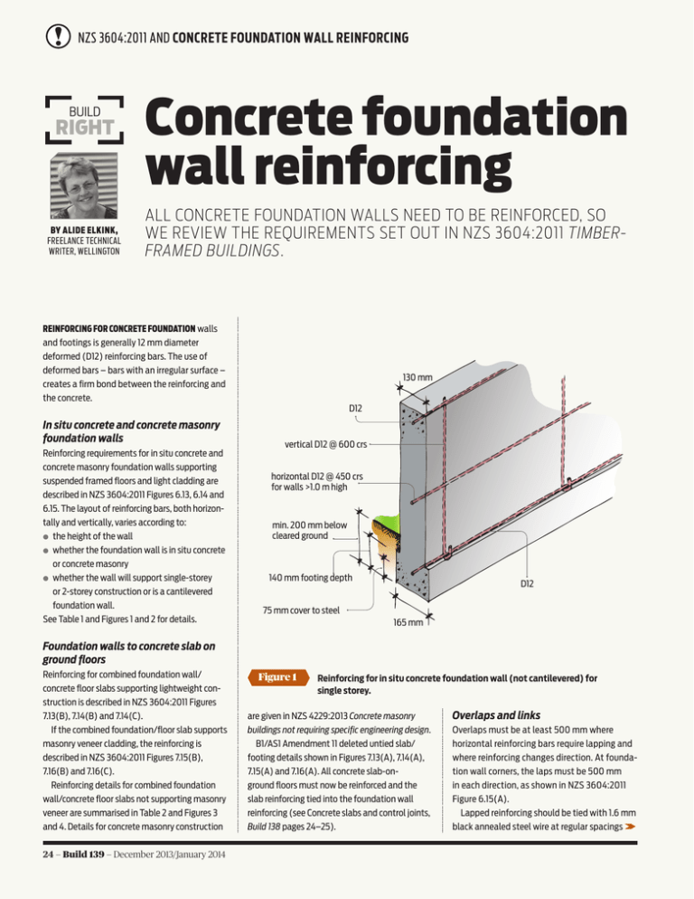
NZS 3604:2011 AND CONCRETE FOUNDATION WALL REINFORCING BUILD RIGHT BY ALIDE ELKINK, FREELANCE TECHNICAL WRITER, WELLINGTON Concrete foundation wall reinforcing ALL CONCRETE FOUNDATION WALLS NEED TO BE REINFORCED, SO WE REVIEW THE REQUIREMENTS SET OUT IN NZS 3604:2011 TIMBERFRAMED BUILDINGS. REINFORCING FOR CONCRETE FOUNDATION walls and footings is generally 12 mm diameter deformed (D12) reinforcing bars. The use of deformed bars – bars with an irregular surface – creates a firm bond between the reinforcing and the concrete. 130 mm D12 In situ concrete and concrete masonry foundation walls Reinforcing requirements for in situ concrete and concrete masonry foundation walls supporting suspended framed floors and light cladding are described in NZS 3604:2011 Figures 6.13, 6.14 and 6.15. The layout of reinforcing bars, both horizontally and vertically, varies according to: ●● the height of the wall ●● whether the foundation wall is in situ concrete or concrete masonry ●● whether the wall will support single-storey or 2-storey construction or is a cantilevered foundation wall. See Table 1 and Figures 1 and 2 for details. vertical D12 @ 600 crs horizontal D12 @ 450 crs for walls >1.0 m high min. 200 mm below cleared ground 140 mm footing depth D12 75 mm cover to steel 165 mm Foundation walls to concrete slab on ground floors Reinforcing for combined foundation wall/ concrete floor slabs supporting lightweight construction is described in NZS 3604:2011 Figures 7.13(B), 7.14(B) and 7.14(C). If the combined foundation/floor slab supports masonry veneer cladding, the reinforcing is described in NZS 3604:2011 Figures 7.15(B), 7.16(B) and 7.16(C). Reinforcing details for combined foundation wall/concrete floor slabs not supporting masonry veneer are summarised in Table 2 and Figures 3 and 4. Details for concrete masonry construction 24 — Build 139 — December 2013/January 2014 Figure 1 Reinforcing for in situ concrete foundation wall (not cantilevered) for single storey. are given in NZS 4229:2013 Concrete masonry buildings not requiring specific engineering design. B1/AS1 Amendment 11 deleted untied slab/ footing details shown in Figures 7.13(A), 7.14(A), 7.15(A) and 7.16(A). All concrete slab-onground floors must now be reinforced and the slab reinforcing tied into the foundation wall reinforcing (see Concrete slabs and control joints, Build 138 pages 24–25). Overlaps and links Overlaps must be at least 500 mm where horizontal reinforcing bars require lapping and where reinforcing changes direction. At foundation wall corners, the laps must be 500 mm in each direction, as shown in NZS 3604:2011 Figure 6.15(A). Lapped reinforcing should be tied with 1.6 mm black annealed steel wire at regular spacings cells with reinforcing filled with concrete D12 @ 400 crs 200 mm 150 mm overlap D12 @ 400 crs Note: Horizontal reinforcing in bond beam @ 800 crs. Figure 2 width = wall height/2 75 mm cover to steel Reinforcing for cantilevered concrete masonry foundation wall for 1 or 2 storeys. Table 1 REINFORCING FOR FOUNDATION WALLS (FRAMED SUSPENDED FLOORS) TYPE OF FOUNDATION WALL In situ concrete Concrete masonry REINFORCING FOOTING AT BASE OF WALL HORIZONTAL IN WALL VERTICAL IN WALL Single-storey 1/D12* (see Figure 1) D12 @ 450 mm crs for walls >1 m high D12 @ 600 mm crs 2-storey 2/D12 D12 @ 450 mm crs for walls >1 m high D12 @ 500 mm crs Cantilevered D12 @ 400 crs both ways D12 @ 400 mm crs max. D12 @ 400 mm crs Single-storey 1/D12* D12 @ at mid height for walls >1 m high D12 @ 800 mm crs 2-storey 2/D12 D12 @ at mid height for walls >1 m high D12 @ 800 mm crs Cantilevered D12 @ 400 crs both ways (see Figure 2) D12 in bond beams @ 800 mm crs max. D12 @ 400 mm crs * 2/D12 where wall supports masonry veneer. Build 139 — December 2013/January 2014 — 25 DPM 400 mm overlap D12 in situ concrete foundation wall grade 500E reinforcing mesh R10 @ 600 crs underslab insulation 75 mm cover to steel DPM sand blinding 200 mm and at each end of the lap. Black annealed steel wire is soft and easily bent. Concrete slabs require pairs of horizontal reinforcing bars in foundation wall footings. These must be linked by stirrups formed from R10 reinforcing bars, installed at 400 mm centres and tied with steel wire at the junctions of the reinforcing and stirrups. Bends in the reinforcing, to form the hook or create a right angle, must have at least five times the diameter of the bar – the minimum bend diameter of a 12 mm diameter deformed reinforcing bar must be no less than 60 mm. Other reinforcing requirements There are a few other reinforcing requirements for foundation walls and footings: ●● Stepped footings must have additional reinforcing in accordance with NZS 3604:2011 Figure 6.12 (see Figure 5). ●● Where concrete or concrete masonry is against ground, reinforcing must have a minimum concrete cover of 75 mm. ●● Openings larger than 300 mm in any direction must have one D12 trimming bar on each side of the opening, which must extend at least 600 mm past each corner of the opening. Where a lintel is less than 650 mm deep, the jamb trimming bars must be bent over 60 mm from the top of the concrete. 26 — Build 139 — December 2013/January 2014 Figure 3 2/D12 compacted hardfill Reinforcing for in situ concrete foundation edge detail for 1 or 2 storeys. 400 mm overlap header block grade 500E reinforcing mesh D12 concrete masonry foundation wall concrete slab underslab insulation over DPM sand blinding 140 mm compacted hardfill DPM folded down inside face of foundation wall 2/D12 240 mm Figure 4 R10 @ 600 crs alternately bent around both footing reinforcing bars Reinforcing for concrete masonry foundation edge detail for 1 or 2 storeys. This is an alternative insulated solution. Table 2 REINFORCING FOR FOUNDATION WALL TO CONCRETE FLOOR SLAB FOUNDATION EDGE DETAIL (SEE FIGURES 3 AND 4) REINFORCING FOOTING AT BASE OF WALL HORIZONTAL IN TOP OF WALL VERTICAL IN WALL LAP (SLAB MESH AND FOOTING REINFORCING) In situ concrete (1 or 2-storey) 2/D12 1/D12 R10 @ 600 mm crs (hooked around horizontal reinforcing) 400 mm In situ concrete (1 or 2-storey supporting masonry veneer) 2/D12 (horizontal) 1/D12 R10 @ 600 mm crs (hooked around horizontal reinforcing) 400 mm Concrete masonry (1-storey – 15 series masonry 2-storey – 20 series masonry) 2/D12 (placed horizontally side by side or stacked vertically) 1/D12 R10 @ 600 mm crs (hooked around horizontal reinforcing in footing in alternating directions) 400 mm Concrete masonry (1 or 2-storey supporting masonry veneer) 2/D12 (horizontal) 1/D12 R10 @ 600 mm crs (hooked around horizontal reinforcing in footing in alternating directions) 400 mm Note: The maximum height of foundation walls is 2 m – this may be increased to 2.6 m measured from underside of footing to top of wall for a length of 1.5 m or less. Refer to NZS 3604:2011 Figure 6.12 for full details. dowel or cast-in bolt or other tested and approved holding-down device DPC under plates and behind stud foundation wall lateral support return end 1.5 m min. length when providing bracing 450 mm min. ventilation opening 600 min. step finished ground level additional D12 reinforcing to step in foundation wall 1.2 m min. and 5 m max. for lateral support (length of step) foundation wall footings must be stepped on sloping sites Figure 5 Reinforcing for stepped footings. Build 139 — December 2013/January 2014 — 27

