Page 1 of 3
<< Back | Print
Reducing EMI/RFI Susceptibility
by Rob Derksen and Bart Bouma, Phycomp/Yageo, and Jim Muccioli and Dave Anthony, X2Y® Attenuators -- 10/1/2003
ECN
This article is also available in a PDF format
The number of peripherals surrounding the modern
computer user continues to increase steadily. Faster
technologies such as CMOS circuits are switching larger
currents, but with reduced voltage margins. As clock
(click image to enlarge)
and data speeds increase, so does a circuit's sensitivity
to noise. For equipment to work together, it is becoming imperative that strict conformity with
electromagnetic interference (EMI) emission limits becomes essential.
For a designer, reducing noise susceptibility and circuit impedance across a broad frequency band means
reducing individual component inductance values. Design-in techniques using a new capacitor have
found that a designer can fundamentally reduce the inductance to the 50 pH range while maintaining low
equivalent series resistance (ESR).
This article will look at board interference, how shielding electrodes can suppress parasitics and improve
broadband circuits with an X and Y capacitor design approach. This approach reduces the number of
decoupling capacitors and improves performance by providing both common and differential-mode
noise suppression for high-frequency signal line filtering.
A New Approach to On-Board Interference
In a conventional setting where a designer is using ferrite bead technology, the on-board interference in
the design is contained by shielding the equipment case. This can mean that the leads entering and
leaving the case are susceptible since they are usually acting as antennas for receiving/transmitting
common mode interference. Any common mode interference due to stray inductance or capacitance
from power and data leads is now generally mopped up by clipping a ferrite bead to one or both ends.
The bead chokes the RFI at the point where it clips onto the lead, providing a high resistance path for the
high-frequency interference. Typically, this sets up current loops that dissipate the energy as heat in the
ferrite core, rather than being transmitted down the cable. In the case of power lines, the ferrite bead
prevents EMI and RFI from being transmitted; and on data lines it prevents any stray interference from
being received.
Ferrite beads deal fairly effectively and easily with the problem, although the EMI suppression they can
achieve is limited. This can be relatively expensive, as it involves a separate assembly operation. A
better approach is to suppress the noise on the circuit board itself. This demands low-inductance
components — particularly capacitors — to isolate critical circuits from ripple and other high-frequency
effects.
In several instances, surface-mount ceramic multilayer capacitors (MLCC) have helped reduce
interference by improving decoupling performance. MLCCs with low-inductance series have been used
successfully to cut interference still further. Located as close as possible to the microprocessor, it can
help keep interference manageable in circuits with process and clock speeds up to approximately 1 GHz.
Above that frequency, the only successful approach is to minimize parasitic inductance and resistance of
http://www.ecnmag.com/index.asp?layout=articlePrint&articleID=CA327377
7/30/2006
Page 2 of 3
critical circuit elements. In this case, a new technology and design-in that offers low-inductance MLCCs
must be accompanied, for critical circuits, by ultra-low-inductance X and Y capacitors to reduce
interference on power and data lines. In the past, discrete components were used, and there is a huge
advantage in integrating them by using this new technology.
Shielding Electrodes Suppress Parasitics
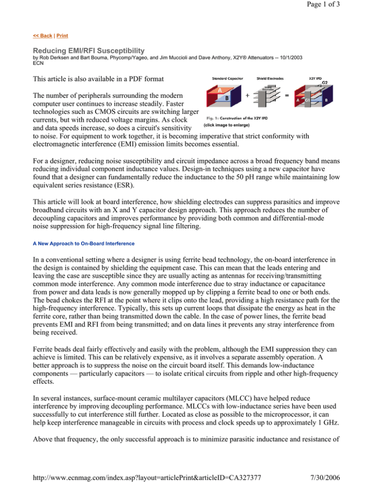
The new design methodology starts from a standard two-electrode (A and B) surface mount capacitor.
Three commonly attached shielding electrodes surround the A/B electrodes, and they connect to two
opposing side terminations (G1 and G2) of the capacitor body. This forms a four-terminal integrated
passive device (IPD) as shown. The electrode shields contain the electrostatic fields, and they suppress
the energy parasitics normally transmitted from the A/B electrodes.
Together with their shield electrodes, the A/B electrodes
create a pair of symmetrically balanced Y capacitors
that act like two standard MLCCs connected to ground.
The same two electrodes also form an 'X capacitor'
across the shared center electrode. In this new design-in,
each Y capacitor has capacitance C, with X being C/2.
As with standard capacitors, repeating the core structure
increases the capacitance.
Figure 1. Construction of Phycomp/Yageo's X2Y IPD
capacitor. (click image to enlarge)
Decoupling Broadband Circuits
Improvements in decoupling have largely been driven by power supplies for high-speed
microprocessors, with CMOS power systems becoming particularly difficult to design1. One
conventional approach identifies target impedance across a broad frequency range and specifies
components to meet that impedance. The required value is falling rapidly (5Ù each computer
generation) and is now down to sub-mÙ levels.
In designs up to approximately 1 kHz, the low impedance is provided by a system's voltage regulator
and at higher frequencies by successively lower-valued capacitors such as bulk capacitors up to 1 MHz,
ceramic up to 1 GHz, and above that by low value capacitors and power planes. Since circuit designers
are continuously tightening layout and component specifications to reduce the target impedance across
the complete frequency range2, the possibility of designing more efficiently and reducing cost is
important.
For a single capacitor, at frequencies above SRF (self resonant frequency), the Xl (inductive) term has
the largest contribution to impedance, and it is determined by the ESL (equivalent series inductance).
Capacitors need to be close to SRF for low impedance, with low capacitance values for decoupling at
high frequency. Given a certain component size, decreasing the capacitance value raises the SRF. This
approach cuts impedances at higher frequencies, and it reduces the decoupling bandwidth. Decreasing
the capacitor's inductance is more effective, increasing the SRF and the effective frequency range.
Signal Line Filtering
Two MLCCs can act as shunt capacitors to give a low-impedance noise path for high-speed signal
filters, with a third MLCC between the two lines filtering differential noise. A single X2Y® replaces all
three MLCCs.
http://www.ecnmag.com/index.asp?layout=articlePrint&articleID=CA327377
7/30/2006
Page 3 of 3
Feed-through capacitors3 improve filtering by reducing
parasitic inductance: two parallel paths shunt noise to
ground. However, the signal current flows through the
capacitor itself: traces, terminations and electrodes all
add DC resistance to cause signal loss. The feed-through
capacitor also has larger parasitic inductance.
Conclusion
A/B electrodes have a remarkable dual function.
Together they form the single X electrode and, with the
shields, they form the two Y electrodes. This allows
Figure 2. Yageo/Phycomp's X2Y IPD capacitor. (click image to
enlarge)
simultaneous operation as both a common- and
differential-mode filter when connected between two
opposing conductors and to ground. A lower inherent inductance improves suppression at higher
frequencies, with broader bandwidth. The internal shield electrodes also provide cross-talk isolation
between pins (line-to-line) for filtering connector lines3, providing better noise filtering than
conventional capacitor designs.
References
1
'Power Distribution System Design Methodology and Capacitor Selection for Modern CMOS
Technology', Larry Smith, Raymond Anderson, Doug Forehand, Tom Pelf, Tammy Roy, IEEE
Transactions on Advanced Packaging, Vol. 22, No. 3, August 1999.
2Carts
Europe 2002, 'X2Y Integrated Passive Devices: A Breakthrough in High-Speed Decoupling and
Broadband Filtering', Rob Derkson, Bart Bouma, Jim Muccioli, Dave Anthony.
3'A
Capacitor's Inductance,' G. Ewell, B. Stevenson, Proceedings of 19th Carts USA, 1999 pp. 186-202.
About the author
For more information, please contact Dave Ritchey at Phycomp/Yageo, 16750 Westgrove Dr., Ste. 600; Addison, TX 75001, (214) 5612033; dave.n.ritchey@yageo.com; www.yageo.com.
<< Back | Print
© 2006, Reed Business Information, a division of Reed Elsevier Inc. All Rights Reserved.
http://www.ecnmag.com/index.asp?layout=articlePrint&articleID=CA327377
7/30/2006


