59T, 66T Series Electric Water Heater Controls - Therm-O-Disc
advertisement
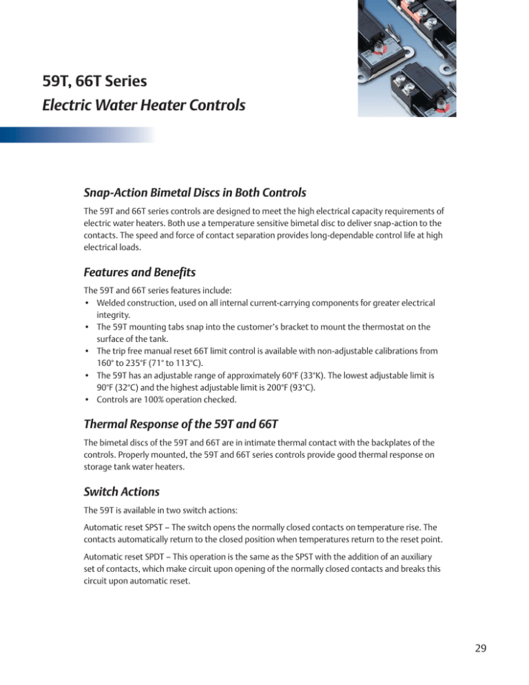
59T, 66T Series Electric Water Heater Controls Snap-Action Bimetal Discs in Both Controls The 59T and 66T series controls are designed to meet the high electrical capacity requirements of electric water heaters. Both use a temperature sensitive bimetal disc to deliver snap-action to the contacts. The speed and force of contact separation provides long-dependable control life at high electrical loads. Features and Benefits The 59T and 66T series features include: • Welded construction, used on all internal current-carrying components for greater electrical integrity. • The 59T mounting tabs snap into the customer’s bracket to mount the thermostat on the surface of the tank. • The trip free manual reset 66T limit control is available with non-adjustable calibrations from 160° to 235°F (71° to 113°C). • The 59T has an adjustable range of approximately 60°F (33°K). The lowest adjustable limit is 90°F (32°C) and the highest adjustable limit is 200°F (93°C). • Controls are 100% operation checked. Thermal Response of the 59T and 66T The bimetal discs of the 59T and 66T are in intimate thermal contact with the backplates of the controls. Properly mounted, the 59T and 66T series controls provide good thermal response on storage tank water heaters. Switch Actions The 59T is available in two switch actions: Automatic reset SPST – The switch opens the normally closed contacts on temperature rise. The contacts automatically return to the closed position when temperatures return to the reset point. Automatic reset SPDT – This operation is the same as the SPST with the addition of an auxiliary set of contacts, which make circuit upon opening of the normally closed contacts and breaks this circuit upon automatic reset. 29 The 66T is a manual reset DPST – The switch opens two sets of normally closed contacts on temperature rise to provide full power disconnect of both conductors. The contacts will reset to the closed position when the reset button is depressed before the control has cooled to 90°F. Once opened, until the reset button is pressed, the contacts will not automatically reset at control temperatures above 32°F (0°C). The construction is classified as “M2 Trip Free” by the approval agencies. This patent pending design holds the contacts open in the event the reset button is held in the depressed position in an attempt to defeat the manual reset function of the thermostat. Typical Application The thermostats and wiring diagram (shown on page 31) are typical of a residential electrical storage water heater installation using two heating elements for non-simultaneous operation. The upper electrical control is a combination 59T SPDT regulating thermostat and a 66T DPST manual reset limiting thermostat. The lower electrical control is a 59T SPST thermostat. All the thermostats sense the surface temperature of the water heater tank. The 66T function is to provide full power disconnect (through both power conductors) in the event of an overheat condition. The 59T SPDT normally closed contacts route power to the upper heating element. When the 59T SPDT control reaches its set temperature, its switch action breaks power to the upper heating element and switches power to the lower heating element through the normally closed contacts of the 59T SPST. When its set point is satisfied, the switch action breaks power to the lower heating element. 30 L 59T SPDT, 66T DPST L2 1 3 66T DPST Limit 1.02 (25.9) 1.59 (40.4) 2 3 1 4 40A,120-277VAC 25A, 480VAC 1 59T SPDT Control T-0-D T R T R ESE 66T 4 2 ESE 125VA, PT.DTY 120-480 VAC 2 4 4 1 4,36 (110.7) Upper Heating Element THERM-O-DISC 59T 2 59T SPST Control Ø0.219 (5.56) 2 Holes 150°F 90°F (66°C) (32°C) 125°F (52°C) 1.03 (26.2) 1.67 (42.4) 0.50 (12.7) 1 2 59T 2.00 (50.8) Lower Heating Element 1.02 (25.9) Figure 1 2.50 (63.5) Double element limited demand circuit for full power disconnect through both power conductors. 59T SPST 1.67 (42.4) 1.02 (25.9) 1 THERM-O-DISC 2.67 (67.8) 2 150°F 90°F (66°C) (32°C) 125°F (52°C) Ø0.219 (5.56) 2 Holes 1.03 (26.2) 59T 2.00 (50.8) 0.50 (12.7) 2.50 (63.5) 31 The thermostats and wiring for single element water heaters are shown below. The combination 59T SPST and 66T DPST is used in residential 240VAC applications, as well as in commercial electric water heater applications where each element may be independently controlled. (see figure 2 below) The combination 59T SPST and 66T DPST can also be used in 120VAC single element installations by leaving terminals 3 and 4 of 66T unutilized. (see figure 3 below) 59T SPST, 66T DPST 1.02 (25.9) 1.59 (40.4) 1 40A, 120-277VAC 25A, 480VAC 3 T-0-D T R T R ESE 66T ESE 125VA, PT.DTY 120-480 VAC 2 4 1 4.36 (110.7) THERM-O-DISC 2 59T 150°F (66°C) 90°F (32°C) 4094 125°F (52°C) 1.67 (42.4) 2.00 (50.8) Ø0.219 (5.56) 2 Holes 1.03 (26.2) 59T 0.50 (12.7) 1.02 (25.9) 2.50 (63.5) L 66T DPST Limit 59T SPST Control L2 1 3 2 4 1 2 Heating Element Figure 2 Figure 3 240VAC Single element circuit for full power 120VAC single element circuit for full power disconnect. disconnect through both power conductors. Dimensions are shown in inches and (millimeters). Dimensions are shown in inches and (millimeters). 32 Calibrations The 59T series temperature regulating controls and the 66T series limit control can be calibrated to meet specific requirements. Typical (industry standard) residential and commercial storage-tank water heater calibrations are shown below. Residential Storage-Tank Water Heaters Type Regulating Adjustable Range Standard Calibration 59T SPST 59T SPDT 90°-150°F (32°-66°C) 90°-150°F (32°-66°C) 120±5°F (49±3°C) 120±5°F (49±3°C) SPST differential 5-15°F (3-8°C) SPDT differential 17-27°F (9-15°C) Type Manual Reset Limit 66T DPST 170±5°F (77±3°C) Commercial Storage-Tank Water Heaters Type Regulating Adjustable Range Standard Calibration 59T SPST 59T SPDT 110°-170°F (43°-77°C) 110°-170°F (43°-77°C) 140±5°F (60±3°C) 140±5°F (60±3°C) SPST differential 5-15°F (3-8°C) SPDT differential 17-27°F (9-15°C) Type Manual Reset Limit 66T DPST 190±5°F (93±3°C) 33 Non-Standard Calibrations The full breadth of calibrations that are available for the 59T and 66T are summarized in the following table. Price adders will apply for these calibrations. 59T REGULATING THERMOSTAT Type Adjustable Range Calibration Range Differential 59T SPST 60°F (33°K) Max 200°F (93°C) Min 90°F (32°C) 5-15°F (3-8°C) 59T SPDT 60°F (33°K) Max 200°F (93°C) Min 90°F (32°C) 17-27°F (9-15°C) 66T LIMIT THERMOSTAT Type Calibration Range Tolerance Reset 66T DPST 235°F (113°C) Min 160°F (71°C) ±5°F (±3°C) M2 Trip Free Non-standard calibrations will utilize dial plates with Low-Medium-High markings. 66TM Options The 66T DPST is available with the 66TM mounting option shown below. The flanges on the backplate allow the 66TM to be screw or stud-mounted. 0.21 (5.3) 1 3 40A,120-277VAC 25A 480 VAC 2.62 T-0-D 2.188 (66.6) 1.63 (41.4) 1.812 (55.58) (46.02) T R T R ESE ESE 125 VA, PT. DTY 120-480 VAC 4 2 1.6 (41) 1.00 (25.4) L235F DATE 301659 66TM 4655 Dimensions are shown in inches and (millimeters). 34 General Electrical Ratings The 59T, 66T series of controls has been rated by major agencies throughout the world. The agency ratings can be used as a guide when evaluating specific applications. However, the mechanical, electrical, thermal and environmental conditions to which a control may be exposed in an application may differ significantly from agency test conditions. Therefore, the user must not rely solely on agency ratings, but must perform adequate testing of the product to confirm that the control selected will operate as intended in the user’s application. Thermostat Type 59T SPST 59T SPDT 66T or 66TM DPST 59 T SPST 66T or 66TM DPST Maximum Calibration Temp 200°F / 93°C 200°F / 93°C 235°F / 113°C 248°F/120°C 248°F/120°C Cycles Pilot Duty VA Resistive Amperes Volts AC 100,000 — 30.0 250 30,000 — 25.0 277 30,000 — 12.5 480 30,000 125 — 120 - 480 30,000 — 30.0 250 30,000 — 25.0 277 30,000 — 12.5 480 30,000 125 — 120 - 480 6,000 — 40.0 277 6,000 — 25.0 480 6,000 125 — 120 - 480 30 — 30.0 250 100 — 16.0 480 30 — 40.0 250 30 — 30.0 400 100 — 16.0 480 Agency & File No. Agency & File No. UL File No. E19279 59T CSA File No. LR10281 UL File No. E19279 59T CSA File No. LR10281 UL File No. E19279 66T CSA File No. LR10281 VDE File # 121213 VDE File # 40014721 NOTE: At thermostat end-of-life, the contacts may remain permanently closed or open. Important Notice Users must determine the suitability of the control for their application, including the level of reliability required, and are solely responsible for the function of the end-use product. These controls contain exposed electrical components and are not intended to withstand exposure to water or other environmental contaminants which can compromise insulating components. Such exposure may result in insulation breakdown and accompanying localized electrical heating. A control may remain permanently closed or open as a result of exposure to excessive mechanical, electrical, thermal or environmental conditions or at normal end-of-life. If failure of the control to operate could result in personal injury or property damage, the user should incorporate supplemental system control features to achieve the desired level of reliability and safety. For example, backup controls have been incorporated in a number of applications for this reason. 35
