Automatic Tuning of Integrated Q
advertisement

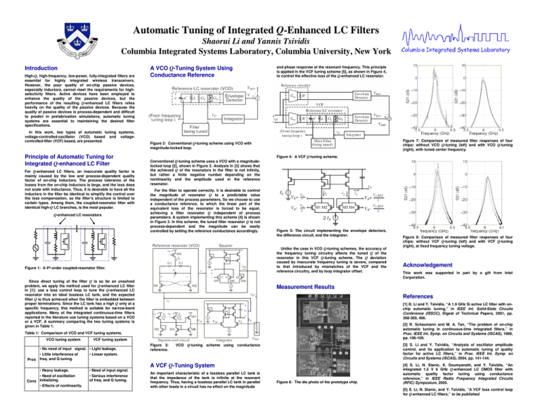
Automatic Tuning of Integrated Q-Enhanced LC Filters Shaorui Li and Yannis Tsividis Columbia Integrated Systems Laboratory, Columbia University, New York Introduction High-Q, high-frequency, low-power, fully-integrated filters are essential for highly integrated wireless transceivers. However, the poor quality of on-chip passive devices, especially inductors, cannot meet the requirements for highselectivity filters. Active devices have been employed to enhance the quality of the passive devices, but the performance of the resulting Q-enhanced LC filters relies heavily on the quality of the passive devices. Because the quality of passive devices is process-dependent and difficult to predict in prefabrication simulations, automatic tuning systems are essential to maintaining the desired filter specifications. In this work, two types of automatic tuning systems, voltage-controlled-oscillator (VCO) based and voltagecontrolled-filter (VCF) based, are presented. Principle of Automatic Tuning for Integrated Q-enhanced LC Filter For Q-enhanced LC filters, an inaccurate quality factor is mainly caused by the low and process-dependent quality factor of on-chip inductors. The process tolerance of the losses from the on-chip inductors is large, and the loss does not scale with inductance. Thus, it is desirable to have all the inductors in the filter be identical to simplify the control over the loss compensation, so the filter's structure is limited to certain types. Among them, the coupled-resonator filter with identical high-Q LC branches, is the most popular. Q-enhanced LC resonators A VCO Q-Tuning System Using Conductance Reference and phase response at the resonant frequency. This principle is applied in the VCF tuning scheme [5], as shown in Figure 4, to control the effective loss of the Q-enhanced LC resonator. Figure 7: Comparison of measured filter responses of four chips: without VCO Q-tuning (left) and with VCO Q-tuning (right), with tuned center frequency. Figure 2: Conventional Q-tuning scheme using VCO with magnitude-locked loop. Conventional Q-tuning scheme uses a VCO with a magnitudelocked loop [2], shown in Figure 2. Analysis in [3] shows that the achieved Q of the resonators in the filter is not infinity, but rather a finite negative number depending on the nonlinearity and the amplitude used in the reference resonator. For the filter to operate correctly, it is desirable to control the magnitude of resonator Q to a predictable value independent of the process parameters. So we choose to use a conductance reference, to which the linear part of the equivalent loss of the resonator is forced to be equal, achieving a filter resonator Q independent of process parameters. A system implementing this scheme [4] is shown in Figure 3. In this scheme, the tuned filter resonator Q is not process-dependent and the magnitude can be easily controlled by setting the reference conductance accordingly. Figure 4: A VCF Q-tuning scheme. Figure 5: The circuit implementing the envelope detectors, the difference circuit, and the integrator. Unlike the case in VCO Q-tuning schemes, the accuracy of the frequency tuning circuitry affects the tuned Q of the resonator in this VCF Q-tuning scheme. The Q deviation caused by inaccurate frequency tuning is severe, compared to that introduced by mismatches of the VCF and the reference circuitry, and by loop integrator offset. Figure 1: A 4th-order coupled-resonator filter. Since direct tuning of the filter Q is so far an unsolved problem, we apply the method used for Q-enhanced LC filter in [1]: use a loss control loop to tune the Q-enhanced LC resonator into an ideal lossless LC tank, and the expected filter Q is thus achieved when the filter is embedded between proper terminations. Since the LC tank has a high Q only at a specific frequency, this method is suitable for narrow-band applications. Many of the integrated continuous-time filters reported in the literature use tuning systems based on a VCO or a VCF. A summary comparing the two tuning systems is given in Table 1. VCO tuning system Pros • Heavy leakage. • Need of oscillation Cons initializing. • Effects of nonlinearity. This work was supported in part by a gift from Intel Corporation. References [1] D. Li and Y. Tsividis, “A 1.9 GHz Si active LC filter with onchip automatic tuning,” in IEEE Int. Solid-State Circuits Conference (ISSCC), Digest of Technical Papers, 2001, pp. 368-369, 466. [2] R. Schaumann and M. A. Tan, “The problem of on-chip automatic tuning in continuous-time integrated filters,” in Proc. IEEE Int. Symp. on Circuits and Systems (ISCAS), 1989, pp. 106-109. VCF tuning system • Need of input signal. • Serious interference of freq. and Q tuning. Acknowledgement Measurement Results Table 1: Comparison of VCO and VCF tuning systems. • No need of input signal. • Light leakage. • Little interference of • Linear system. freq. and Q tuning. Figure 8: Comparison of measured filter responses of four chips: without VCF Q-tuning (left) and with VCF Q-tuning (right), at fixed frequency tuning voltage. Figure 3: reference. [3] S. Li and Y. Tsividis, “Analysis of oscillator amplitude control, and its application to automatic tuning of quality factor for active LC filters,” in Proc. IEEE Int. Symp. on Circuits and Systems (ISCAS), 2004, pp. 141-144. VCO Q-tuning scheme using conductance A VCF Q-Tuning System An important characteristic of a lossless parallel LC tank is that the impedance of the tank is infinite at the resonant frequency. Thus, having a lossless parallel LC tank in parallel with other loads in a circuit has no effect on the magnitude Figure 6: The die photo of the prototype chip. [4] S. Li, N. Stanic, K. Soumyanath, and Y. Tsividis, “An integrated 1.5 V 6 GHz Q-enhanced LC CMOS filter with automatic quality factor tuning using conductance reference,” in IEEE Radio Frequency Integrated Circuits (RFIC) Symposium, 2005. [5] S. Li, N. Stanic, and Y. Tsividis, “A VCF loss control loop for Q-enhanced LC filters,” to be published.


