Oil/Air Cooler Units: Compact Design & High Performance
advertisement
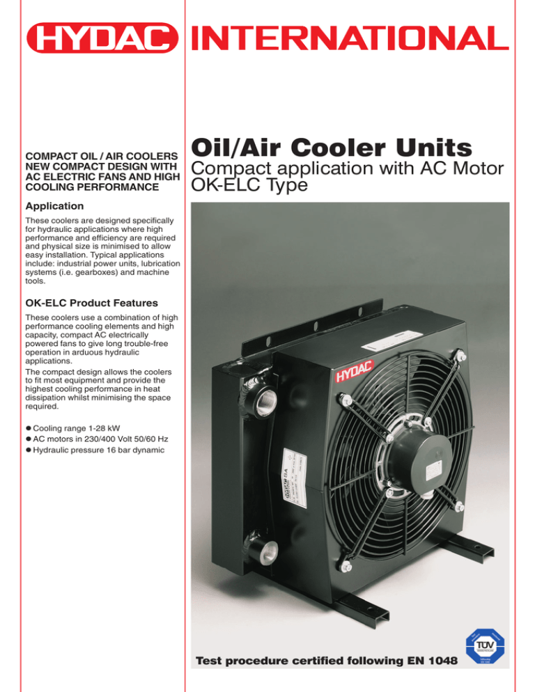
COMPACT OIL / AIR COOLERS NEW COMPACT DESIGN WITH AC ELECTRIC FANS AND HIGH COOLING PERFORMANCE Oil/Air Cooler Units Compact application with AC Motor OK-ELC Type Application These coolers are designed specifically for hydraulic applications where high performance and efficiency are required and physical size is minimised to allow easy installation. Typical applications include: industrial power units, lubrication systems (i.e. gearboxes) and machine tools. OK-ELC Product Features These coolers use a combination of high performance cooling elements and high capacity, compact AC electrically powered fans to give long trouble-free operation in arduous hydraulic applications. The compact design allows the coolers to fit most equipment and provide the highest cooling performance in heat dissipation whilst minimising the space required. z Cooling range 1-28 kW z AC motors in 230/400 Volt 50/60 Hz z Hydraulic pressure 16 bar dynamic Test procedure certified following EN 1048 OIL/AIR COOLER ELC 0 ELC 0 DESCRIPTION GENERAL In hydraulic systems energy is transformed and transmitted. During this transformation and transmission losses occur, i.e. mechanical and hydraulic energy is converted into heat. It is the function of the cooler to dissipate this heat. ADVANTAGES OF THE OIL/AIR COOLERS: z Environmentally friendly. No exchange between water and oil possible z For commissioning only electrical energy is required z Low operating costs, no additional cooling circuit necessary for the cooling medium, i.e. air CONSTRUCTION Oil/air cooler units consists of the (1) heat exchanger, (2) housing (3) axial motor fan. The oil connections are on the rear side. 2 PASS ELC 1 ELC 1 ELC 2-5 ELC 2-5 ELC 6-7 ELC 6-7 2 Cooler selection: – Desired oil temperature: 60 °C – Ambient temperature air: 30 °C PV T1 - T3 4.78 = 60 - 30 P01 = P01 [kW/°C] = 0.159 [kW/°C] A 10% safety margin is recommended to allow for element contamination, and therefore the specific power is: P01 × 1.1 = 0.175 kW/°C. The power loss 0.175 kW/°C must be dissipated by an oil cooler. Suggestion: –Cooler OK-ELC3H, P01 = 0.2 kW/°C at 40 l/min Example 2: The power loss can also be estimated. With unrestricted flow approx. 15 to 20% of the drive power. With restricted flow up to 30% of the drive power. ELC0H ELC1H ELC1H ELC2H ELC2H ELC3H ELC3H ELC4S ELC4S ELC5S ELC5S ELC6H ELC6H ELC7S ELC7S 35 120 115 120 140 170 188 210 230 210 230 2X 170 2X 188 2X 210 2X 230 2800 2700 2600 2600 2500 2600 2500 1400 1380 1400 1380 2600 2500 1400 1380 – 2/450 2/500 2/450 2/500 4/450 3/500 4/450 – 4/450 – 2X 4/450 2X 3/500 2X 4/450 – 20 55 55 55 55 55 55 55 55 55 55 55 55 55 55 59 71 71 71 71 75 75 69 69 72 72 75 75 71 71 16 16 16 16 16 16 16 16 16 16 16 16 16 16 16 130 130 130 130 130 130 130 130 130 130 130 130 130 130 130 2000 2000 2000 2000 2000 2000 2000 2000 2000 2000 2000 2000 2000 2000 2000 Weight [kg] Max. Viscosity [mm²/s] Max. oil temperature [°C] Max. operating pressure [bar] Noise level [dB(A)] (at 1m distance) Protection class IP [-] 2 2 2 2 2 2 2 4 4 4 4 2 2 4 4 Capacitor [µF/VDB] 20 120 120 210 210 220 220 190 190 270 270 180 180 140 140 Speed at 50 Hz [rpm] 230 230 400 230 400 230 400 230 400 230 400 230 400 230 400 Motor Capacity at 50Hz [W] TABLE OF TECHNICAL SPECIFICATIONS N° of poles 1.1. Oil flow at 1.5 bar pressure drop [l/min] ∆T × coil × ρoil × V [kW] t × 60 25 × 1.88 × 0.915 × 100 = 4.78 [kW] PV = 15 × 60 PV = TECHNICAL DETAILS Voltage [V] Designation: PV = Power loss [kW] P01 = Specific cooling capacity [kW/°C] V = Tank contents [l] ρoil = Density of the oil [kg/l] for mineral oil: 0.915 kg/l Coil = Specific heat capacity [kJ/kgk] for mineral oil 1.88 kJ/kgk ∆T = Temperature increase in the system [°C] t = Operating time [min] T1 = Desired oil temperature [°C] T3 = Ambient temperature [°C] Example 1: Measurement of the power loss on existing units and machinery. For this method the temperature increase of the oil is measured over a certain period. The power loss can be calculated from the temperature increase. Parameters: The oil temperature increases from 20 °C to 45 °C over 15 minutes. The tank contains 100 l. Heat to be dissipated: 1. Type of cooler COOLER SELECTION 3.2 9 9 11.9 11.9 14.7 14.7 21 21 28 28 39 39 45 45 – ELC0: the electrical connection wires are provided – ELC1-7: the electrical connection box is included – Capacitor is supplied with the cooler and mounted in the connection box when required – All motors with IP55 have protection class F, except ELC0 with IP20 – Mounting position: all positions possible – For direction of rotation see arrow on cooler housing – Cooling fluid Mineral oil to DIN 51524 For other fluids, please contact our sales/technical department – The noise levels are only a guide as acoustic properties vary and depend on the characteristics of the room, connections, viscosity and resonance. – Options: see accessory catalogue Warning! When operating a cooler in situations where the difference in temperature between ambient air and inlet oil exceed 50 Deg. Celsius, care must be taken to avoid cycling of the fan at full speed/air flow as this can cause rapid change in material temperature of element and may result in significant reduction in lifetime or direct damage to the element through thermal stress. Please contact your Hydac Branch or distributor for speed control solutions. 3 1.2. HYDRAULIC DETAILS 1.2.1 Cooling capacity depending on oil flow and the temperature differential ∆T between the oil inlet and air inlet. For calculations with low ∆T values (i.e. below 10 °C), please contact our technical support staff. Tolerance: ± 5% 30 Heat dissipation at ∆T = 40 °C [kW] 25 0.6 ELC 6H 20 0.5 ELC 5S 0.4 15 ELC 4S 10 0.3 ELC 3H 0.2 ELC 2H ELC 1H 5 0.1 ELC 0H 0 0 50 100 150 Specific heat dissipation [kW/°C] * 0.7 ELC 7S 0 250 200 Oil flow [l/min] * Values measured at ∆T = 40 °C, may vary at lower ∆T values 1.2.2 Pressure differential ∆p measured at 30 mm²/s using mineral oil Tolerance: ± 5% 2.4 Pressure drop at 30 mm²/s [bar] 2.2 ELC 7 ELC 0 ELC 1 ELC 6 2.0 1.8 ELC 4 1.6 1.4 ELC 2 1.2 ELC 3 ELC 5 1.0 0.8 0.6 0.4 0.2 0.0 0 50 100 Oil flow [l/min] 150 200 250 For other viscosities the result must be multiplied by K Viscosity (mm2/s) Factor K 10 0.35 15 0.5 22 0.75 30 1 46 1.4 68 1.9 100 2.5 150 3.5 4 2. MODEL TYPE (also order example) OK-ELC2H / 1.0 / 230V / 1 / S / AITF50 Type of cooler OK-ELC = Oil/air cooler Size / motor speed 0:7 = See hydraulic details 1.2 H = 3000 min-1 S = 1500 min-1 Type code and modification number Electrical motor fan voltage 230V = 230 Volts 50/60 Hz 400V = 400 Volts 50/60 Hz Paint 1 = RAL 9005 (Standard) Other paint on request and clearly written Air flow direction S = Suction (Standard) Accessories (for more information see accessories brochure ) AITF50 = Thermostat (fixed) IBP = Heat exchanger with integrated bypass valve (not available for ELC0 and ELC1) IBT = Heat exchanger with integrated thermo-bypass valve (not available for ELC0 and ELC1) GP = Vibration absorber 5 3. DIMENSIONS 3.1. ELC0 B ±10 C1 ±4 C2 ±4 D1 ±1 D2 ±2 D3 ±2 E1 ±2 E2 ±5 W1 min W2 min Z1 F 4xØ ELC0 202 138 240 220 60 190 80 72 79 150 50 G1/2" 6.5 3.2. ELC1 PLU G A1 ±5 ELC1 A1 ±5 B ±10 C1 ±8 D1 ±2 D2 ±2 D3 ±2 D4 ±2 E1 ±5 E2 ±5 E3 ±5 W1 min W2 min Z1 F 6xØ Plug 300 205 340 110 270 136 50 200 65 300 200 70 G3/4" 8.5 M22X1.5 6 ELC2-5 PLU G 3.3. A1 ±5 B ±10 C1 ±5 D1 ±2 D2 ±3 D3 ±3 E1 ±5 E2 ±5 E3 ±5 E4 ±2 E5 ±2 W1 min W2 min Z1 F 6xØ Plug ELC2 328 295 384 255 160 295 199 72 324 288 80 250 150 G1" 14x10 M22X1.5 ELC3 371 287 420 255 240 295 230 78 370 329 100 300 180 G1" 16x9 M22X1.5 ELC4 465 292 500 255 255 295 289 96 450 421 150 400 200 G1" 16x9 M22X1.5 ELC5 475 306 602 255 255 295 350 70 490 200* 580* 400 250 G1 1/4" 12 M22X1.5 * : ELC5 has the front fixing holes in the lateral sides. ELC6-7 PL UG 3.4. A1 ±5 B ±10 C1 ±8 D1 ±3 D2 ±3 D3 ±3 E1 ±5 E2 ±5 E3 ±5 E4 ±2 E5 ±2 W1 min W2 min Z1 F 8xØ Plug ELC6 495 286 810 255 482 295 321 91 750 450 170 400 200 G1 ¼" 16x9 M22X1.5 ELC7 547 289 950 255 482 295 373 94 890 503 200 503 250 G1 ¼" 18x9 M22X1.5 4. CERTIFICATION FOLLOWING EN 1048 Hydac SA design and manufacture high quality coolers that are tested and certified to give reliable and repeatable high performance. To ensure the performance is accurate, testing in compliance with a recognized international test standard is the best solution. For air/liquid coolers this is EN1048. Hydac SA test procedure complies with the requirements of EN 1048 and both the procedure and test equipment are independently inspected and certified by TÜV SÜDDEUTSCHLAND. The cooler performance details in this brochure have been tested following EN 1048. 5. NOTE The information in this brochure relates to the operating conditions and applications described. For applications or operating conditions not described, please contact the relevant technical department. Subject to technical modifications. 7
