Protected by one or more US Patents: 8915613; D702,391; D702,390; D700,732
HP-4 Recessed with Regressed Lens 9/16" T-bar Starter/Independent
Installation Instructions
FINELITE
Step 1
Step 2
Step 3
Step 4
Center-to-center T-Grid spacing.
#8-18 x1/4" Screws
(provided)
Lens
Brackets
1"
#6-20 x 1/2" Self Drilling
Screws (provided)
(provided)
4 5/8"
For 9/16" T-bars
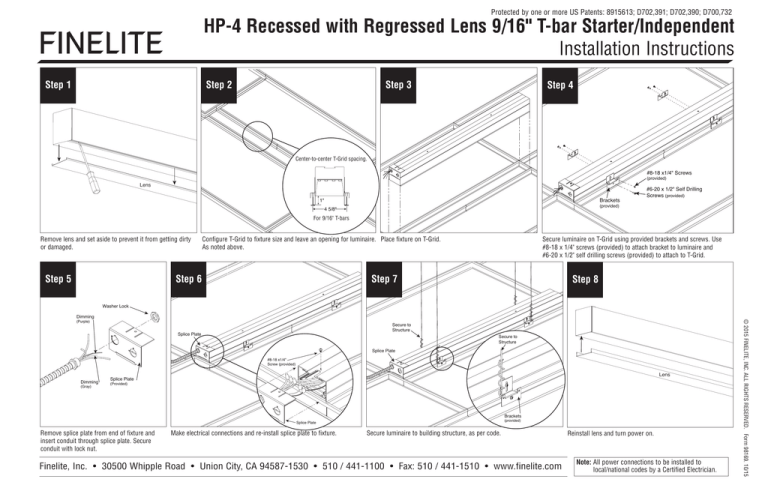
Remove lens and set aside to prevent it from getting dirty
or damaged.
Step 5
Configure T-Grid to fixture size and leave an opening for luminaire. Place fixture on T-Grid.
As noted above.
Step 6
Secure luminaire on T-Grid using provided brackets and screws. Use
#8-18 x 1/4" screws (provided) to attach bracket to luminaire and
#6-20 x 1/2" self drilling screws (provided) to attach to T-Grid.
Step 7
Step 8
Washer Lock
(Purple)
Secure to
Structure
Splice Plate
Secure to
Structure
Splice Plate
#8-18 x1/4"
Screw (provided)
Dimming
(Gray)
Lens
Splice Plate
(Provided)
Brackets
(provided)
Splice Plate
Remove splice plate from end of fixture and
insert conduit through splice plate. Secure
conduit with lock nut.
Make electrical connections and re-install splice plate to fixture.
Secure luminaire to building structure, as per code.
Finelite, Inc. • 30500 Whipple Road • Union City, CA 94587-1530 • 510 / 441-1100 • Fax: 510 / 441-1510 • www.finelite.com
Reinstall lens and turn power on.
Note: All power connections to be installed to
local/national codes by a Certified Electrician.
© 2015 FINELITE, INC. ALL RIGHTS RESERVED. Form 98169. 10/15
Dimming
Protected by one or more US Patents: 8915613; D702,391; D702,390; D700,732
HP-4 Recessed with Regressed Lens 9/16" T-bar Joiner
Installation Instructions
FINELITE
Step 1
Step 2
Step 3
Step 4
Joiner
Plate
Joiner/Ender
Plug
Together
Wiring
Starter
Starter
Joiner
Plate
Center-to-center T-Grid spacing.
1"
Remove lens and set aside to prevent it from getting dirty
or damaged.
Step 5
Starter
For 9/16" T-bars
Configure T-Grid to fixture size and leave an opening for
luminaire. As noted above.
IMPORTANT STEP
End Brackets
Joiner/Ender
Place fixture on T-Grid.
Connect Plug Together Wiring and align joiner/ender with joiner plate and
carefully slide starter and joiner/ender together.
Joiner/Ender
Step 6
Plug Together
Wiring
Step 7
Washer Lock
Dimming
Secure to
Structure
(Purple)
#6-20 x 1/2" Self Drilling
Screws (provided)
Starter
#8-18 x 1/4"
Screws (provided)
#8-18 x 1/4"
Screws (provided)
Brackets
(provided)
Dimming
#6-20 x 1/2"
Self Drilling Screws
(Gray)
Bracket (provided)
Install 2 #8-18 x 1/2" Combo Hex Screws (provided) into end bracket as shown.
Screws can be installed from the left or right.
Secure all fixtures to T-Grid by driving #6-20 x 1/2" self drilling screws (provided) through brackets into
T-Grid. Connect all fixtures to building structure, as per code. Use #8-18 x 1/4" screws (provided) to
install brackets on fixtures.
Splice Plate
(Provided)
Remove splice plate from end of the fixture and insert conduit
through splice plate and secure.
Finelite, Inc. • 30500 Whipple Road • Union City, CA 94587-1530 • 510 / 441-1100 • Fax: 510 / 441-1510 • www.finelite.com
Note: All power connections to be installed to
local/national codes by a Certified Electrician.
© 2015 FINELITE, INC. ALL RIGHTS RESERVED. Form 98170. 10/15
#8-18 x 1/2" Combo Hex
Screw (provided)
Starter
4 5/8"
Lens
Protected by one or more US Patents: 8915613; D702,391; D702,390; D700,732
HP-4 Recessed with Regressed Lens 9/16" T-bar Joiner
Installation Instructions
FINELITE
Step 8
Step 9
#8-18 x 1/4"
Screw (provided)
Splice
Plate
Lens
Splice Plate
Make electrical connections and re-install splice plate to fixture.
Reinstall lens and turn power on.
Note: All power connections to be installed to
local/national codes by a Certified Electrician.
© 2015 FINELITE, INC. ALL RIGHTS RESERVED. Form 98170. 10/15
Finelite, Inc. • 30500 Whipple Road • Union City, CA 94587-1530 • 510 / 441-1100 • Fax: 510 / 441-1510 • www.finelite.com


