Technical Information Paper
Output Voltage Holding Time
■General Description
■Calculation Example
Set input and output conditions as shown in the figure
below.
Power circuits hold the output voltage for some time even
when power supplied at the input block from an external
source is interrupted. This duration is referred to as the
“output voltage holding time.”
Backup circuits used with microcomputers or RAM are also
voltage-holding circuits. A large-size capacitor, lithium
battery, or the like is used for this purpose depending on the
length of time required to hold voltage. In the case of a
capacitor, its capacitance is greatly related to the length of
backup time.
This paper explains the relationship between output voltage
holding time and the capacitance of a capacitor.
VIN=5.0V, VOUT=3.3V,IOUT=0.15A,η=0.8
Output Voltage holding time (t):0.07s
First, determine the output power (WOUT).
WOUT=VOUT×IOUT
=3.3×0.15
=0.495[W]
Next, obtain the input power (WIN) required to hold
WOUT = 0.495 [W].
WIN=WOUT÷η
=0.495÷0.8
=0.61875
≒0.62[W]
■Principle
Holding an output voltage is achieved by energy
stored in the output capacitor. However, if a load is
connected to the output, energy stored in the output
capacitor is always discharged as a load current.
Discharge characteristics determined by the time
constant of the RC circuit exert an influence on the
voltage holding time.
If, in a booster circuit, a short output voltage holding
time and drop in the output voltage do not constitute
a matter of concern, the capacitance of the output
capacitor can be increased as a simple method.
If a drop in the output voltage should be avoided, the
capacitance of the input capacitor can be increased.
As the input capacitor serves as a power source if
power supplied from an external source stops, the
circuits continue to operate normally without
producing any drop in the output voltage.
Energy stored in a capacitor within a unit time is
expressed by the following equation.
The capacitance of the input capacitor (CIN) meeting this
input power requirement is determined by the following
equation.
Substituting VIN = 5.0 [V], WIN = 0.62 [W],
and t = 0.07 [s] in this equation, we obtain:
Hence, if CIN = 30 [mF] or higher, it is possible to hold the
output voltage even when power supplied from an output
source stops for 0.07[s].
Note: Regarding the capacitance of a capacitor,
the lower tolerance derived from the
nominal value should be taken into
account.
This equation expresses that the stored energy depends
highly on the voltage applied to the capacitor and the
capacitance of the capacitor.
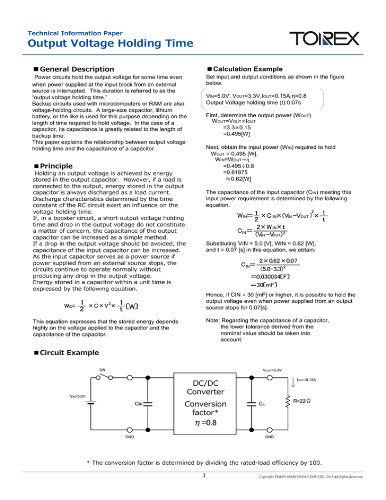
■Circuit Example
SW
VOUT=3.3V
IOUT=0.15A
DC/DC
DC/DC
Converter
コンバータ
VIN=5.0V
CIN
Conversion
factor*
*変換率
R=22Ω
CL
η=0.8
GND
GND
* The conversion factor is determined by dividing the rated-load efficiency by 100.
1
Copyright TOREX SEMICONDUCTOR LTD. 2015 All Rights Reserved.


