Radiated Emission and Susceptibility
advertisement

Radiated Emission and Susceptibility
Tzong-Lin Wu, Ph.D.
EMC Lab
Department of Electrical Engineering
National Taiwan University
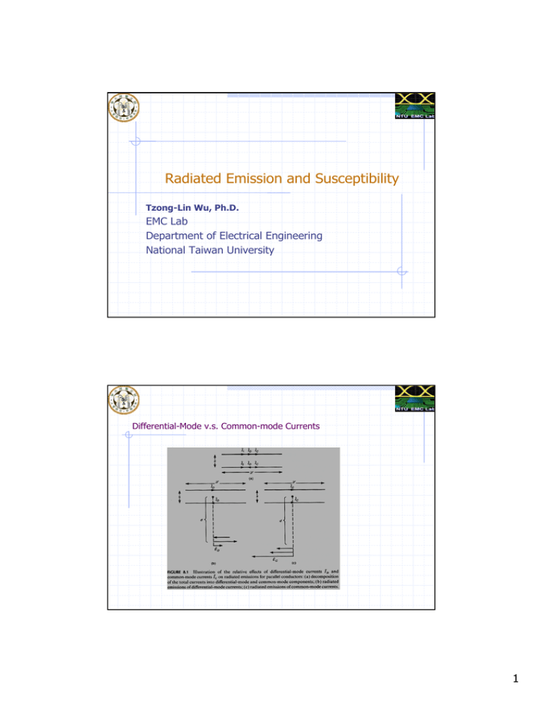
Differential-Mode v.s. Common-mode Currents
1
Differential-Mode v.s. Common-mode Currents
Eθ = Eθ ,1 + Eθ ,2
? e
= M? ( I1
= M ( I1
e
− j β 0 r1
r1
+ I2
− j β 0 ( r +Δ )
e − j β0 r2
) F (θ )
r2
+ I2
e − j β0 ( r −Δ )
) F (θ )
r−Δ
r+Δ
e − j β0r
( I1e− j β0 Δ + I 2 e j β0 Δ ) F (θ )
=M
r
M is a function of antenna type
F(θ) is the array factor
η0 β 0
⎧
l = j 2π ×10−6 fl
⎪M = j
4π
⎨
For Hertzian dipole
⎪⎩
F (θ ) = sin θ
Differential-mode current emission model
A Question: Where is the maximum E field for the differential current ?
z
θ
x
2
Differential-mode current emission model
Θ=90 is the maximum
Differential-mode current emission model
I1 = I d
I2 = −Id
fI D l − j β0 d − j β0 s / 2
e
{e
− e j β0 s / 2 }
d
I f 2ls
= 1.316 × 10⁻¹⁴ D
d
Ed ,max = j 2π ×10−7
1.
2.
Reduce the loop size
Reduce the current level
Can reduce the EMI
3
Differential-mode current emission for trapezoidal pulse train
EMI due to the differential-mode current is
significant for higher frequencies.
An example
1m ribbon cable with 50mil distance carrying 20mA current at 30MHz
The EMI at 3m distance is about
40dBuV/m
It’s easy to over the FCC limit line
4
Why the slot increase EMI ?
15cm
15cm
12.5cm
5mm
30cm
30cm
Common-mode Emission Model
I1 = I c
I2 = Ic
fI c l − j β0 d − j β0 s / 2
e
{e
+ e j β0 s / 2 }
d
I fl
= 1.257 × 10⁻⁶ c
d
Ed ,max = j 2π × 10−7
1.
2.
Reduce the trace length
Reduce the current level
Can reduce the common-mode EMI
5
An Example
1m ribbon cable with 50mil distance carrying 7.96uA current at 30MHz
The EMI at 3m distance is about
40dBuV/m -> limit of FCC
Very small current will exceed the limit of FCC !
Common-mode current emission for trapezoidal pulse train
Common-mode EMI usually occurs
at low frequency range
6
Current Probe for common-mode current
Working principal ?
Ampere’s Law and
Faraday Law are both used in
the design
Calibration data:
Zt = V / I
(transfer impedance)
Why only common-mode current are
Sensed in this probe?
Current Probe Example
7
Examples for common-mode EMI
James L. Knighten et al., “Experimental Analysis of Common Mode Currents on
Fiber Channel Cable Shields due to Skew Imbalance of Differential Signals
Operating at 1.0625 Gb/s”, IEEE EMC Symposium, 1999
Lothar 0. Hoeft et al., “Spectral Analysis of Common Mode Currents on
Fiber Channel Cable Shields due to Skew Imbalance of Differential
Signals Operating at 1.0625 Gb/s”, IEEE EMC Symposium, 1998
James L. Knighten et al., “Effects of Device Variations on the EMI Potential of
High Speed Digital Integrated Circuits”, IEEE EMC Symposium, 1997
Decomposition of the Common/Differential mode
8
Delay Skew effect on the Spectral components (1st harmonic)
Rise time is a minor effect on the spectral component
Skew effect on the Spectral components (1st harmonic)
9
Measurement setup for EMI and Common-mode current
Delay Skew design on PCB
10
Measurement Results for Common-mode current and their radiation
Fundamental Frequency
EMI increases about 9dB/decade
of the skew
Common-mode current v.s. EMI (measurement)
Fundamental Frequency
11
Delay Skew v.s. Common-mode current (measurement)
Higher harmonics
Questions:
•
Why does 3rd harmonic not increase
as skew increases ?
•
Why does 2nd harmonic exist ?
Delay Skew v.s. Common-mode current
Increasing delay skew will increase the energy of 3rd harmonic.
But, impedance mismatch between trace on PCB and Cables increase
the reflection coefficient.
Therefore the common-mode current of 3rd harmonic on the cable decreases.
12
About the Even harmonics
1st harmonic
2nd harmonic
Lack of symmetry of the waveform causes the even harmonics
Measurement setup for digital waveform
13
Digital waveform and its spectrum
Even harmonics
Asymmetry of the waveform may be resulted from
• Difference of the rise/fall times
• Not 50% duty cycle (shorter or longer)
EMI for higher harmonics
14
Common-Mode EMI on the Ground Plane
A trace on a solid Ground plane
Common-Mode EMI on the Ground Plane
Equivalent Circuit
Common-mode Noise
It can be reduced by increasing
the mutual inductance
How ?
15
Common-Mode EMI on the Ground Plane
Reducing trace Height
To increase Mgs
Common-Mode EMI on the Ground Plane
Adding another return path
to decrease I2
Guard trace
Shunt trace
16
Common-Mode EMI on the Ground Plane
Resonant effect by
Image Plane
Radiated Susceptibility
Area of uniform field
Interconnection filter
Incoming mains power filter
Field generation antenna
(1.5m×1.5m)
0.8m
Field
generation
equipment
3m
Interconnecting cables
Chamber penetration cables
17
Radiated Susceptibility
Test levels for radiated immunity
( 80 MHz to 1000 MHz)
Level
Test field strength
V/m
1
1
2
3
3
10
x
Special
NOTE – x is an open test level. This level
may be given in the product specification.
The signal is 80 % amplitude modulated
with 1 kHz sinewave to simulate actual
treats.
8-2 Simple Susceptibility Models for wires and PCB Lands
a.Modelling a two conductor line to determine the terminal voltages
induced by incident eletromagnetic field.
Ei
y
y
L
x
z
+
RS
Incident wave
_
+
VS
S
The problem is:
VL
_
RL
Hi
x
predicting the VS and VL given the magnitude,polarization ,and direction of
the incident uniform plane wave(Ei , Hi)
_
18
b.Only two components of incident wave contribute to the induced voltage.
Ei = E
⊗ −H
E yi
S
RS
equivalent Tx line model
I ( x)
RS
S
where
per-unit-length
L=
RL
i
z
n
(
i
z
(induce)
I ( x + x)
L
X
+
V (X )
_
μ0
s
n(
)
π
rω
C = πε 0
Hi = H
i
y
C
IS
X
X
RL
for parallel-wire line
s
)
rω
c.V s ( x ) , I s ( x ) = ?
(1)by the Faraday's law ⇒ the incident magnetic field
H zi will induce the emf in the loop.
emf = jω ∫ B zi i d S
s
=-jωμ 0 ∫ H zi i dS = - jωμ 0 x ∫
s
y =0
H zi dy
s
∴ per-unit-length source at x , V s ( x ) =
s
emf
= - jωμ 0 ∫ H zi dy
=0
y
x
(2)The incident E yi induces a voltage between the two conductors
,which induces a displacement current in the per-unit-length
capacitance C.
∴ Is ( x) = - jωC ∫
s
y =0
E yi dy
19
d .Derive the tx-line equations
V( x + x) − V( x) = − jω L xI ( x) − V( x) x
I ( x + x) − I ( x) = − jωC xV( x + x) + I S ( x) x
Dividing x , and x → 0
⇒
s
dV( x)
+ jω LI ( x) = − VS ( x) = + jωμ 0 ∫ H zi dy
y =0
dx
s
d I ( x)
+ jωC V( x) = I S ( x) = - jωC ∫ E yi dy
=0
y
dx
e. if the tx-line is electrically short = L λ 0
the , C can be ignored
jωμ 0 H zi i A
+
RS
+
- jωCE yi i A VL
_
VS
_
RL
∴ total source
VSL = jωμ 0 ∫
s
y =0
I SL = - jωC ∫
s
y =0
H zi dy ≅ jωμ 0 H zi i S i L = jωμ 0 H zi i A
S
area
L λ0
E dy ≅ - jωCE yi i S i L = - jωCE yi i A
i
y
S
L λ0
20
f.∴ It is easy to compute the induced voltage VS and VL
RS
RSRL
jωμ 0 LSH zi −
jωCLSE yi
RS + RL
R S + RL
RL
RSRL
jωμ 0 LSH zi −
jωCLSE
VL = −
RS + RL
RS + RL
g.An example:
VS =
+
50Ω
i
y
+
50mil
VS
−
VL
150Ω
−
Ei = 10 v
m
f = 100MHz
1m
(1)only magnetic field induce voltage source.
(2)VS = jωμ 0 LSH ni A = j × 2π × 108 × 4π × 10−7 ×
Ei
× 1m × 1.27 × 10−3
70
= j 26.6mv
(3)
j 26.6mv
+
50Ω
VS
150Ω
−
50
j 26.6mv = j 6.65mv
50 + 150
150
j 26.6mv = − j 20mv
VL = −
50 + 150
VS =
21
Radiated Susceptibility for a transmission line
Example (1):
What kind of noise will couple to the transmission line ?
Radiated Susceptibility for a transmission line
Voltage noise source
22
Radiated Susceptibility for a transmission line
Example 2
Radiated Susceptibility for a transmission line
Example 3. Current Injection Technique in Conducted Susceptibility Test
Can this technique replace the R.S. test ?
“Investigation of the Bulk Current Injection Technique by Comparison to Induced Currents from Radiated
Electromagnetic Fields”, IEEE EMC Symposium, p412 – p417, 1996
23
Radiated Susceptibility for a transmission line
Testing probes and their working principle
Radiated Susceptibility for a transmission line
Test Plate for generating uniform EM wave
24
Radiated Susceptibility for a transmission line
Uniform field check
Radiated Susceptibility for a transmission line
Three different cases
25
Radiated Susceptibility for a transmission line
1 Ohm case
They are quite consistent below
100MHz
Measured under BCI technique
Measured under Parallel Plate
Calculated by previous theory
Radiated Susceptibility for a transmission line
270 Ohm case
50 Ohm Case
Summary: BCI technique can be used in low frequency range to complement the
high frequency radiation susceptibility test
26


