Document
advertisement

Induction
In 1830-1831, Joseph Henry & Michael Faraday discovered electromagnetic
induction. Induction requires time varying magnetic fields and is the subject of another
of Maxwell's Equations.
Modifying Ampere's Law to include the possibility of time varying electric fields gives
the fourth Maxwell's Equations.
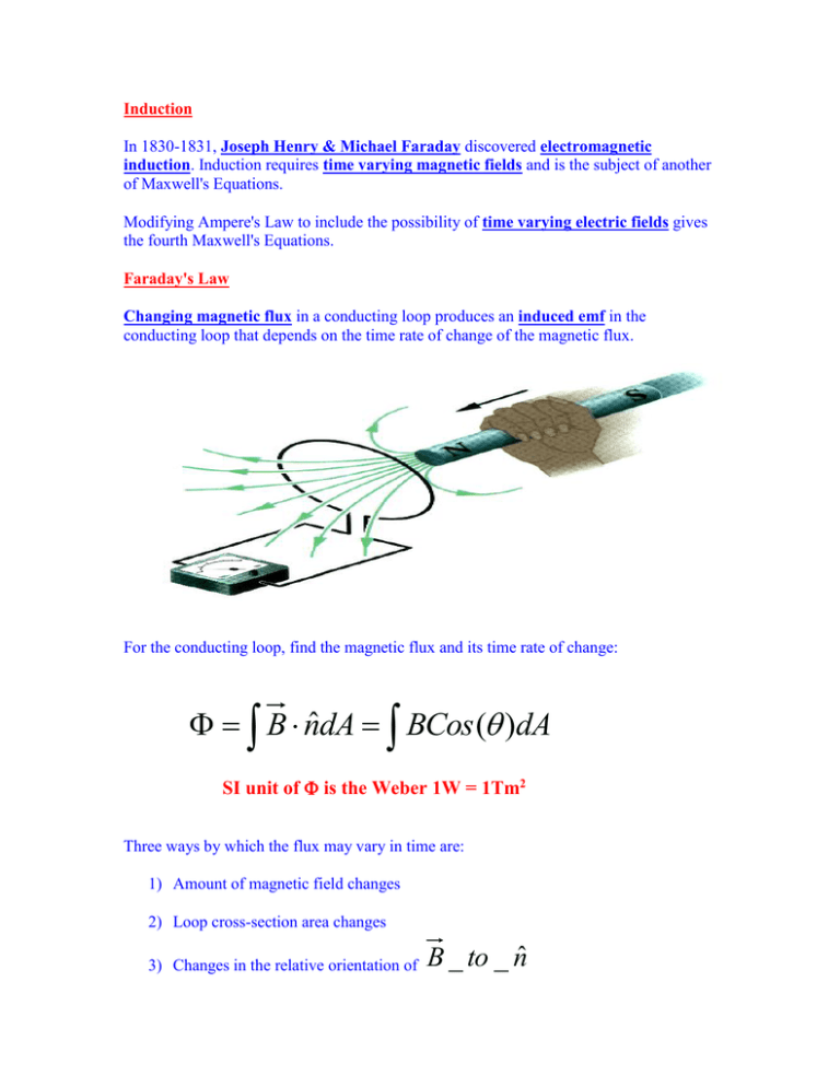
Faraday's Law
Changing magnetic flux in a conducting loop produces an induced emf in the
conducting loop that depends on the time rate of change of the magnetic flux.
For the conducting loop, find the magnetic flux and its time rate of change:
B nˆdA BCos ( )dA
SI unit of is the Weber 1W = 1Tm2
Three ways by which the flux may vary in time are:
1) Amount of magnetic field changes
2) Loop cross-section area changes
3) Changes in the relative orientation of
B _ to _ nˆ
Method 3) is used in an electric generator with input mechanical energy.
Effectively the opposite of an electric motor, the changing orientation of the loop
relative to
B results in a generated emf via induction in the conducting loop.
For a changing magnetic flux, the induced emf in the conducting loop is:
Emf
d
dt
In an AC generator, if the loop rotates at a constant angular velocity
Emf
:
d
d
BA Cos(t ) BASin (t )
dt
dt
Using a coil with
N tightly packed loops,
Emf NBASin(t ) E0 Sin(t )
n̂
Emf
Note the minus sign in the induced emf:
d
dt
The minus sign implies the direction of flow for the electric current resulting from the
induced emf. This is described by Lenz's Law.
Lenz's Law
Lenz's Law is: The direction of current corresponding to the induced emf is such that the
magnetic field resulting from this current opposes the change in magnetic flux that
induces the current.
A changing magnetic field flux
Induced current direction is such that its
B field direction opposes flux field changes.
E.g., A time varying
B
B 4t 2 x 2 (kˆ)
established in area HxW defined by a conducting wire loop
Find the induced emf at time
t .10s
Y
W=3
H=2
Z
X
3
3
2 2
2 x
B nˆdA 4t x Cos( ) Hdx 4 Ht { } 72t 2
3 0
Emf
Increasing
d
144t
dt
At _ t 0.1s
Emf 14.4V
B into the page implies current will be counterclockwise.
Motional Emf
For a circuit or loop of wire moving within a magnetic field, changing magnetic flux can
induce an emf because of the conductor motion.
As the loop is removed from the region of magnetic field, a '_________' current is
induced. Moreover, since this is a current carrying wire in a magnetic field, a force
F BiL is present on each of the segments within the field.
Along the top and bottom portions of the wire, these forces cancel. However, the external
agent must supply power
P F v to move the loop within the magnetic field
since the force on the vertical segment of wire in the field is directed opposite to
v.
FExt
E
BL d BL d
B 2 L2v
BiL B * * L
*
* ( BXL )
R
R dt
R dt
R
B 2 L2v 2
P FvCos(0)
R
Rate of doing work to move the loop at
v.
E 2 B 2 L2 v 2
Pi R
R
R
2
The resistive heat in the loop is also
Fixing the loop in place, emf can be generated by moving a rail on a U-shaped conductor:
L
V
Electric Potential and Time Varying Magnetic Fields
Within a time varying magnetic field, the possibility of induced emf subverts Kirchhoff's
loop rule:
V E ds 0
Instead
E ds
d
dt
Note electric potential has lost meaning when electric fields are the result of time varying
magnetic fields. Forces associated with changing magnetic fields are not conservative.
Counter Emf, Counter Torque, and Eddy Current
In the case of an electric motor, as the driving current turns coils within the magnetic
field there is an emf generated in the conducting loops that has current opposing the
supply current. This is the back emf and depends on the rotation rate of the coils.
For the electric generator, an attached load draws current through the generator coils,
which produces a counter torque at the axel.
Eddy currents form in general when a conductor moves through a region of magnetic
field such that forces exist on the free electrons in that material. Eddy currents require
energy that is extracted from the moving conductor thereby having a dissipating effect.
Ampere-Maxwell Law
Faraday's Law says a changing magnetic flux induces emf or, changing magnetic fields
produce electric fields. A question then arising is, does an induction of magnetic field
result from changing electric fields?
The answer is yes and is quantified in the fourth and last of Maxwell's equations called
the Ampere-Maxwell Law:
d E
B dl 0ienc 0 0 dt
Ampere's Law is regained if the electric flux is constant in time.
i
If enc
0 but electric flux changes, then Maxwell's Law of Induction results.
The 2nd term on the RHS is
0 * Displacement _ Current 0id
id 0
d E
dt
This neither is a 'current' nor involves displacement but references the fictional ether.
The displacement current is not an actual current in the sense of charge flow, but the
analogy is marginally supported through an example of a charging circular capacitor:
As a parallel plate capacitor attached to an emf is charged, the field in the gap between
the two conducting plates increases from zero to V/d. This represents a changing E.
In the gap there is, say, a vacuum and therefore no conducting wires for a 'current' proper.
i
0
That is, enc
in the gap region. The electric flux is changing and there are both
electric and magnetic fields in the gap during the charging process of the capacitor.
As the capacitor charges, charge on the conducting plates is evaluated using Gauss's Law:
The 'real' current is
The displacement current is
i
dq
dE
0 A
dt
dt
d E
d
id 0
EA i
dt
0 dt
ii
Therefore,
d and displacement current is thus viewed as an extension of 'real'
current through the capacitor gap region such that Ampere's law in this region gives:
d E
B dl 0ienc 0 0 dt 0id ,enc
r 2
B 2r 0 2 id
R
B 0
r
i
2 d
2R
Inside
Maxwell's Equations in Integral Form for Free Space
Gauss's Law for Electric Fields
Gauss's Law for Magnetic Fields
Faraday's Law of Induction
Ampere-Maxwell Law
E nˆdA
qenc
0
B nˆdA 0
d B
E dl dt
B dl 0ienc 0 0
d E
dt
Superconductivity
Discovered in 1911 by H.K. Onnes, superconductivity is the loss of all electrical
resistance by an element, inter-metallic alloy or compound below a certain critical
temperature Tc.
The highest Tc is 138 K seen in a ceramic material thallium-doped, mercuric-cuprate
comprised of the elements Mercury, Thallium, Barium, Calcium, Copper and Oxygen
138 K is well above the 77 K liquid Nitrogen boiling point, which makes ceramic
superconductors economically attractive. Current formability and strength issues
represent technological barriers for High Tc superconductors.
Type 1 category superconductors are mainly metals that require liquid Helium
temperatures around 4 K in order to establish "Cooper pair" formation and a
superconducting transition. The formation is a "phonon-mediated coupling" involving
sound packets generated by the flexing material lattice. The theory describing this type of
superconductivity is BCS.
Lead (Pb)
Lanthanum (La)
Tantalum (Ta)
Mercury (Hg)
Tin (Sn)
Indium (In)
Thallium (Tl)
Rhenium (Re)
Protactinium (Pa)
Thorium (Th)
Aluminum (Al)
Gallium (Ga)
Molybdenum (Mo)
Zinc (Zn)
7.196 K
4.88 K
4.47 K
4.15 K
3.72 K
3.41 K
2.38 K
1.697 K
1.40 K
1.38 K
1.175 K
1.083 K
0.915 K
0.85 K
Type 1 superconductors will expel any external applied magnetic field from its interior
while in a superconducting state (Meissner Effect), but may also be brought back into a
normal state if the external magnetic field is greater than a critical value Bc.
Type 2 superconductors are metallic compounds, metal-oxide ceramics, and alloys. They
achieve higher Tc's than Type 1 superconductors that may be due to conduction from
positively charged vacancies within the lattice called Holes.
Type 2 superconductors allow some penetration by an external magnetic field into its
surface that produces thin filaments of normal phase material, oriented parallel to the
applied field, around which currents circulate.
Type 2 superconductors have higher Bc making these more useful in applications where
high fields are needed.
Two Bc exist for Type 2 superconductors: Bc1 is the field value at which external fields
enter the material and Bc2 is the field value when the material returns to a normal phase.
Hg0.8Tl0.2Ba2Ca2Cu3O8.33
138 K
HgBa2Ca2Cu3O8
133-135 K
HgBa2Ca3Cu4O10+
125-126 K
HgBa2Ca1-xSrxCu2O6+
123-125 K
HgBa2CuO4+
94-98 K


