ATNF InP HBT CIRCUITS SUMMARY
advertisement
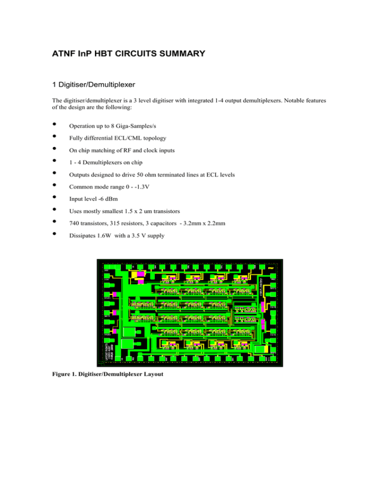
ATNF InP HBT CIRCUITS SUMMARY 1 Digitiser/Demultiplexer The digitiser/demultiplexer is a 3 level digitiser with integrated 1-4 output demultiplexers. Notable features of the design are the following: • • • • • • • • • • Operation up to 8 Giga-Samples/s Fully differential ECL/CML topology On chip matching of RF and clock inputs 1 - 4 Demultiplexers on chip Outputs designed to drive 50 ohm terminated lines at ECL levels Common mode range 0 - -1.3V Input level -6 dBm Uses mostly smallest 1.5 x 2 um transistors 740 transistors, 315 resistors, 3 capacitors - 3.2mm x 2.2mm Dissipates 1.6W with a 3.5 V supply Figure 1. Digitiser/Demultiplexer Layout 2. Digitiser The Digitiser is a 3 level digitiser without integrated demultiplexer. This design was principly included as a backup in case yields were low causing the more complex Digitiser/Demultiplexer to be unsuccessful. Features of this design are: • • • • Operation up to 8 GS/s Contains no demultiplexer 119 transistors, 57 resistors and 3 capacitors 350 mW on a 1.6mm x 1.2mm die Figure 2. Digitiser Layout. 3. Photonic I/O Digitiser The Photonic I/O digitiser is a 3 level digitiser with sampling clock supplied photonically and the ability to return the digitised data photonically. Notable features of this design are: • • • • • • Sampling clock supplied photonically Digital data returned photonically On-chip photodiode and transimpedance amplifier Current switching output drivers for driving external laser diodes or MZMs 116 transistors, 59 resistors and 3 capacitors 700 mW on a 1.6mm x 1.2mm die Figure 3. Photonic I/O Digitiser Layout. 4 Multiplier The multiplier is a wideband 4 quadrant Gilbert cell multiplier intended for analogue correlator applications. Features of the design are: • • • • • Optimised for linearity Fully DC coupled differential inputs and outputs 15 GHz multiplication bandwidth and 11 GHz IF output bandwidth 24 transistors, 21 resistors and 2 capacitors 110 mW with 1V amd -3V supplies on a 1.2mm x 1.2mm die Figure 4. Multiplier Layout. Further information can be found at http://www.atnf.csiro.au/people/proberts/inp/inp.html or by email from Paul.Roberts@atnf.csiro.au
