VTLN IN THE MFCC DOMAIN - Center for Language and Speech
advertisement

VTLN IN THE MFCC DOMAIN: BAND-LIMITED VERSUS LOCAL INTERPOLATION
Ehsan Variani†, Thomas Schaaf‡
†CLSP, Johns Hopkins University, Baltimore MD 21218, USA
‡M*Modal, Pittsburgh, USA
Variani@jhu.edu, tschaaf@mmodal.com
ABSTRACT
(a)
We propose a new easy-to-implement method to compute a Linear Transform (LT) to perform Vocal Tract Length Normalization
(VTLN) on truncated Mel Frequency Cepstral Coefficients (MFCCs)
normally used in distributed speech recognition. The method is
based on a Local Interpolation which is independent of the Mel
filter design. Local Interpolation (LILT) VTLN is theoretically and
experimentally compared to a global scheme based on band-limited
interpolation (BLI-VTLN) and the conventional frequency warping scheme (FFT-VTLN). Investigating the interoperability of these
methods shows that the performance of LILT-VTLN is on par with
FFT-VTLN and BLI-VTLN. Models trained with LILT- and BLIVTLN performance degrades if FFT-VTLN is used as a front-end.
The degradation for LILT-VTLN is slightly less, indicating that it
produces models that are a better match for FFT-VTLN.
Index Terms— Automatic speech recognition, VTLN, frequency warping, linear transform
1. INTRODUCTION
Vocal Tract Length Normalization (VTLN) improves the accuracy of
automatic speech recognition (ASR) systems by reducing the effect
of vocal tract length differences. To control the change of spectra,
a single parameter, α, called the warping factor is estimated using
the following maximum likelihood (ML) technique for each speaker
[10],
α∗ = arg max {log P r(Xiα |λ, Ui ) + log |Aα |}
α
(1)
where Xiα is the warped feature vector, λ is the HMM parameters
and Ui is the ith utterance. In this equation |Aα | is the Jacobian of
the normalization which theoretically is necessary since the likelihood of the warped features is calculated with respect to the previous assumed distribution. This makes the likelihood more comparable for different warping factors. Since it is very difficult to obtain
a closed-form solution for α∗ in the above equation, some optimization technique is used. In practical ASR systems α is between 0.8
and 1.20 which comes from the physiological data [1].
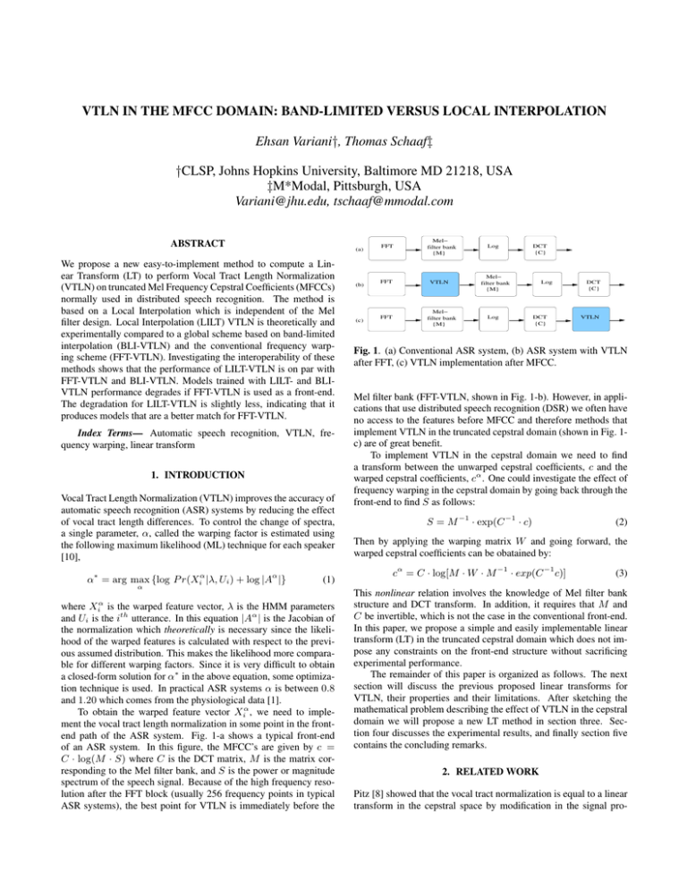
To obtain the warped feature vector Xiα , we need to implement the vocal tract length normalization in some point in the frontend path of the ASR system. Fig. 1-a shows a typical front-end
of an ASR system. In this figure, the MFCC’s are given by c =
C · log(M · S) where C is the DCT matrix, M is the matrix corresponding to the Mel filter bank, and S is the power or magnitude
spectrum of the speech signal. Because of the high frequency resolution after the FFT block (usually 256 frequency points in typical
ASR systems), the best point for VTLN is immediately before the
(b)
(c)
FFT
FFT
FFT
Mel−
filter bank
{M}
VTLN
Mel−
filter bank
{M}
Log
DCT
{C}
Mel−
filter bank
{M}
Log
Log
DCT
{C}
DCT
{C}
VTLN
Fig. 1. (a) Conventional ASR system, (b) ASR system with VTLN
after FFT, (c) VTLN implementation after MFCC.
Mel filter bank (FFT-VTLN, shown in Fig. 1-b). However, in applications that use distributed speech recognition (DSR) we often have
no access to the features before MFCC and therefore methods that
implement VTLN in the truncated cepstral domain (shown in Fig. 1c) are of great benefit.
To implement VTLN in the cepstral domain we need to find
a transform between the unwarped cepstral coefficients, c and the
warped cepstral coefficients, cα . One could investigate the effect of
frequency warping in the cepstral domain by going back through the
front-end to find S as follows:
S = M −1 · exp(C −1 · c)
(2)
Then by applying the warping matrix W and going forward, the
warped cepstral coefficients can be obatained by:
cα = C · log[M · W · M −1 · exp(C −1 c)]
(3)
This nonlinear relation involves the knowledge of Mel filter bank
structure and DCT transform. In addition, it requires that M and
C be invertible, which is not the case in the conventional front-end.
In this paper, we propose a simple and easily implementable linear
transform (LT) in the truncated cepstral domain which does not impose any constraints on the front-end structure without sacrificing
experimental performance.
The remainder of this paper is organized as follows. The next
section will discuss the previous proposed linear transforms for
VTLN, their properties and their limitations. After sketching the
mathematical problem describing the effect of VTLN in the cepstral
domain we will propose a new LT method in section three. Section four discusses the experimental results, and finally section five
contains the concluding remarks.
2. RELATED WORK
Pitz [8] showed that the vocal tract normalization is equal to a linear
transform in the cepstral space by modification in the signal pro-
cessing of the conventional front-end. McDonough [6], used the
all-pass transform to derive a linear transform for VTLN (without
considering DCT-II) in the continuous frequency domain which requires access to the all cepstral coefficients. Uebel [12] showed that
direct frequency warping and the all-pass transform lead to similar
improvements in VTLN. He used a matrix approximation technique
that learns the mappings between the truncated warped cepstral features and the unwarped features. This is computationally expensive,
sensitive to noise in the training data, only practical for a fixed number of warp factors, and requiring large amounts of training data.
Claes [2] proposed another VTLN transform by assuming the
warping factor, α, is small enough to allow the approximation of
the logarithm with a linear function which is only valid for warping
factors close to zero. They also approximated the right inverse of the
Mel-filter bank matrix. To solve the problem of non invertibility of
the Mel transform, Cui [3] approximated the Mel filter matrix and
its inverse using index matrices. These are matrices in which each
row contains exactly one non-zero value which is one. Assuming the
warping matrix W is also an index matrix, and then plugging them
into Eq. (2) they introduced the following linear transform,
cα = (C · M · W · M −1 · C −1 )c
(4)
Then they set this linear transform, which was derived by warping
in the physical frequency domain, equal to the transform derived
by warping in the Mel domain. But these two transforms are not
identical because of the non-linear behavior of the logarithm [10].
Panchapagesan [7] also did this and incorporated the warping into
the DCT matrix implementing the VTLN transform. Depending on
the warping parameter, the index matrix approximation described in
[3, 7] causes singular matrices, leading to difficulties in computing
the Jacobian. In addition, they used a different configuration of the
Mel filter bank during the approximation, which can result in a larger
mismatch between the expected features.
Umesh [13] and Sanand [10, 9] also proposed the following linear transform,
α
T[k,n]
=
2N −1
α
2π ( vl )k j 2π ( vl )n
1 X −j 2N
vs
e
e 2N vs
2N
(5)
l=0
where vs is the sampling frequency in the Mel domain, vlα , and vl
denote the Mel frequencies after and before the warping, respectively, and N denotes the number of Mel filters. This transform
is based on the band-limited interpolation (BLI-VTLN) for reconstructing the continuous signal from its uniformly spaced samples.
The first question about this method is whether the conditions for
Shannon band-limited interpolation are satisfied. The main issue is
the presence of the logarithm which is not a band-limited operator
and it is not clear that we could apply this theorem to its output
values. In addition the interpolation uses 2N points to prohibit the
appearance of imaginary parts, but there is no sample point at zero
frequency or at the Nyquist frequency (because there is no Mel filter at these frequencies). To solve this difficulty, Sanand [10, 1] adds
half filters at these points which is not common in typical front-ends.
Further it is shown in [9] that similar results could be achieved without these half filters, but this approach seems to be sensitive to noise.
In addition to achieving better global interpolation and higher resolution in the frequency domain, a large number of Mel filters are used,
which is different from conventional ASR systems. One of the significant advantages of this approach is its straightforward calculation
of the Jacobian matrix, which is done in [10].
3500
3000
2500
2000
v6
v 6α
v5
v 5α
v4
v 4α
1500 v (mel)
1000
v3
v 3α
500
v 2α
v2
0
−500
−1000
v 1α
v1
f 1αf 1 f 2αf 2
0
f 3α f 3
1000
f 4α
2000
3000
f4
4000
f 5α
f (H z)
5000
f 6α
f5
6000
7000
f6
8000
9000
10000
Fig. 2. The Mel function makes the vlα non-equidistant, and allows
them to be within one mel interval of the vl , (α = 0.80).
3. PROPOSED LINEAR TRANSFORM
In this section, we want to create a mathematical framework for understanding the effect of VTLN on the Mel filter bank coefficients
after the logarithm. At this point we have N points corresponding to the N filters of the Mel filter bank. Let the mel frequency
be vl = 2595 log (1 + f /700). The warped mel frequency is
vlα = 2595 log (1 + α(f )/700), where α(f ) is the warping function. Because of this non linear relation, it is clear that the warped
Mel frequencies may not be equidistant. Fig. 2 illustrates this point
by plotting vlα versus the center frequencies of some Mel filter bank
in the physical frequency domain.
Our math problem is finding the corresponding log-Mel coeffiα
cients values after warping, mα
l , corresponding to vl based on the
current log-Mel coefficients ml corresponding to vl where 1 ≤ l ≤
N . One idea is to use a global interpolation approach by estimating the function that goes through all previous points and using that
function to find the values of mα
l . Band limited interpolation, discussed in the previous section, is one possible global interpolation.
However, the additional information from distant filters may hurt
performance, making local interpolation preferable.
By taking a careful look at Fig. 2, we see that each warped Mel
frequency is within one mel interval of the corresponding unwarped
Mel frequency. This motivated the idea of local interpolation to find
α
the value of mα
l for the corresponding vl in the Mel domain. The
first degree of local interpolation is the linear interpolation which
interpolates the output of two consecutive filters by a straight line,
according to the following equation,
mα
l = λl mil + (1 − λl )mil +1
(6)
where il is the index corresponding to the Mel filter in the left side
of the warped mel frequency vlα , and
λl = (vil +1 − vlα )/(vil +1 − vil )
for the first and last coefficients we always consider the two first
and two last filters, respectively. By finding the parameter λl for all
filters we can compute the linear transform as:
for j = il
λl
α
T[l,j]
= 1 − λl for j = il + 1
(7)
0
otherwise
The final linear transform corresponding to local linear interpolation
(LILT-VTLN) is given by:
α
−1
Aα
N ×N = CN ×N · TN ×N · CN ×N
(8)
2
Read
Speech
118
340
1.5
1
Audio (h)
Speakers
0.5
Broadcast
News
106
5238
Medical
Reports
334
212
Total
559
5790
0
Table 1. English training database.
−0.5
−1
0
500
1000
1500
Mel Frequency
2000
2500
3000
Fig. 3. Comparison of the log-Mel coefficients: before warping (circles), after warping (diamonds), and the estimated values by linear
interpolation (crosses).
Fig. 3 shows the mel coefficients of a random speech frame before warping, the estimated coefficients after warping using the interpolation, and the real values of the coefficients after warping. It
is easy to see that linear interpolation tracks the real warped values
very well and in some points gives even the exact same values.
The linear interpolation gives a very simple and straightforward
approach for implementing vocal tract length normalization after
MFCC. One of the main advantages of this technique is its independence of the configuration of the front-end, in particular the Mel
filter bank. In addition, it does not use any kind of modification of
the Mel filters. Additionally, the Jacobian of this matrix is relatively
easy to compute and is plotted in Fig. 5. Further improvements of
the local interpolation can be achieved by increasing the number of
filter banks; however it is unclear if this is also beneficial for speech
recognition.
4. EXPERIMENTAL DESIGN
The following experiments were designed to investigate how compatible the different VTLN methods (FFT-VTLN, LILT-VTLN, BLIVTLN) are. In an ideal case they could be easily exchanged during
training and testing without changing the Word Error Rate (WER). It
should be noted that the BLI-VTLN [9] was implemented assuming
half-filters since otherwise a warp of 1.0 would not result in the identity matrix. We were concerned that this would change the features
in an incompatible way. The comparison between LILT-VTLN and
BLI-VTLN allows us to assess how critical the interpolation method
is.
All recognizers were trained from an English training set consisting of audio from read speech, Broadcast News, and medical
reports; some details are given in Table 1. Read speech is an inhouse database similar to Wall Street Journal, Broadcast News data
is from LDC, and the medical reports is a sub-set of in-house data
from various medical specialties. Since the medical reports were
spoken by physicians with the intention of being transcribed by a
human, the speech style was conversational, with hesitations, corrections and extremely fast speech. The acoustic conditions are also
very challenging, since neither the quality of the microphone nor
the environment were controlled, resulting often in rather poor audio quality with a large amount of background noise. The medical
reports were recorded at 11kHz, all other data were down-sampled
to 11kHz. More details can be found in [11]
All four acoustic models in the experiments (with and without
VTLN) used the same phonetic context tree with 3000 tied-states,
that were Maximum Likelihood trained with a global semi-tied covariance [4] with about 42k Gaussians. This relatively small model
size was chosen to increase the expected improvements from VTLN
allowing an easier comparison of the performance. In all front-ends
a cepstral mean and variance normalization was performed during
training and decoding. A piecewise linear warping function consisting of two linear segments mapping the zero and the Nyquist frequency to themselves with an edge at 80% was used. The Mel filter
bank had 30 filters equally spaced starting after an initial gap of 125
Hz. The speaker warp factor was trained using a target model with
a single Gaussian for which the warp and model were re-estimated
over three iterations.
The development set used in decoding experiments consisted of
nine physicians (two female) from various medical specialties with
15k running words in 37 medical reports. Decoding experiments
used a single-pass decoder with a standard 3-state left-to-right HMM
topology for phonemes and a single state for noises. Since the focus
was on comparing the front-ends a single general medical 4-gram
Language Model was used for all reports during decoding. Warp
factors were estimated during an initial decoding run using a grid
search from 0.8 to 1.2 with an increment of 0.01. For all test speakers
the warp was between 0.9 and 1.15.
The first experiment, shown in Table 2, investigated whether the
FFT-VTLN could be exchanged with a LILT-VTLN or BLI-VTLN.
Assuming compatibility of the front-ends, there should be no significant change in performance and we should be able to use the warp
factors found with the FFT-VTLN. For each acoustic model a fixed
set of warp factors derived with the FFT-VTLN was used during this
experiment. First, using VTLN gave a 5% relative error reduction
which is in the normal range for VTLN. The matched pair sentence
segment significance test from the NIST sclite tool showed that improvements from using VTLN were statistically significant, but did
not find a significant difference between different VTLN implementations.
WER
Acoustic Model
no VTLN
FFT-VTLN
no VTLN
16.84%
-
Decoding Front-End
FFT
BLI
16.40% 16.50%
15.92% 15.97%
LILT
16.44%
15.94%
Table 2. Decoding without matching warp factors.
In our next experiment we analyzed the warp factors estimated
during training and found that both LILT- and BLI-VTLN have, on
average, a warp factor that is about 0.01 larger than warps found by
FFT-VTLN. Interestingly, the warp histograms in Fig.4 shows that
the LILT-VTLN results in a more compact warp distribution, while
the BLI-VTLN matches the FFT-VTLN closer. The BLI-VTLN exhibits more extreme warp factors up to 1.6. Although we performed
a variance normalization, proper explicit Jacobian compensation as
Eq.1 might be needed, since otherwise LILT prefer the warp factors
between 0.9 and 1.1. Similar discussion may hold for BLI, while it
has a weak preference for extreme warp factors.
In our final experiment we combined the different acoustic models with the different VTLN implementations during decoding, and
estimated the optimal warp factor for each speaker and combination.
1000
FFT−VTLN
LILT−VTLN
BLI−VTLN
900
800
700
600
500
400
300
200
100
0
0.8
0.9
1
1.1
α
1.2
1.3
1.4
1.5
Fig. 4. Warp histograms for FFT-, LILT-, and BLI-VTLN.
3
LILT−VTLN
BLI−VTLN
2
6. REFERENCES
1
log |A α |
speech recognition. We compared our approach with conventional
VTLN and the band-limited interpolation approach. The experimental results show that in matched condition all the approaches work
similarly. Yet, in non matched conditions, where the conventional
front-end is used by the acoustic model which was trained with the
presence of linear transform in the cepstral domain, both approaches
degenerate but LILT-VTLN still is more compatible to the conventional VTLN. It is possible that the interpolation technique that maximizes compatibility with the FFT-VTLN is something in between
LILT-VTLN which only considers the information of two filters and
BLI-VTLN, which considers the information of all Mel filters.
0
−1
−2
0.8
0.85
0.9
0.95
1
α
1.05
1.1
1.15
1.2
Fig. 5. Jacobian (log determinant) for LILT-VTLN and BLI-VTLN.
Table 3 shows that both methods that perform a linear transform
of the truncated MFCC perform slightly better than the FFT-VTLN;
however the difference is not statistically significant. When the
acoustic model was trained on LILT-VTLN or BLI-VTLN, and FFTVTLN was used as the front end, a degradation was found which was
statistically significant for BLI-VTLN (p=0.012) and LILT-VTLN
(p=0.011). This degradation indicates that the LILT-VTLN and BLIVTLN might not be as compatible with the FFT-VTLN as we wish;
however the LILT-VTLN model seems to be more compatible.
WER
Acoustic Model
no VTLN
FFT-VTLN
BLI-VTLN
LILT-VTLN
no VTLN
16.84%
-
Decoding Front-End
FFT
BLI
16.40% 16.50%
15.92% 15.72%
16.45% 16.04%
16.26% 15.90%
LILT
16.44%
15.81%
16.07%
15.91%
Table 3. Decoding with matching warp factors.
Overall, the LILT-VTLN system was as compatible with the
FFT-VTLN warp factors and acoustic model as the BLI-VTLN system was. This leads to the conclusion that it is not critical which
interpolation is performed as long as it gives a reasonable approximation of the Mel-spectrum.
5. CONCLUSION
We proposed a new approach for implementing vocal tract length
normalization in the truncated cepstral domain. Local Interpolation
Linear Transform VTLN (LILT-VTLN1 ) is an elegant and easily implementable technique which has the advantage of being less dependent on the front-end structure, in particular the design of the Mel
filter bank. It does not assume or require an equidistance property of
the Mel filters in the Mel domain or the introduction of half-filters (in
contrast to other methods such as band-limited interpolation VTLN).
This is relevant when, for example, the Mel filter bank is designed
with a gap at the lower frequency as is often used in telephony
1 Lilt: A cheerful or lively manner of speaking, in which the pitch of the
voice varies pleasantly
[1] Akhil, P. T., Rath, S. P., Umesh, S., Sanand, D. R., 2008. “A
computationally efficient approach to warp factor estimation in
VTLN using EM algorithm and sufficient statistics”. In: Proceedings of Interspeech 2008, pp. 1713-1716.
[2] Claes, T., Dologlou, I., ten Bosch, L., Van Compernolle, D.,
1998. “A novel feature transformation for vocal tract length
normalization in automatic speech recognition”. IEEE Trans.
on Speech and Audio Processing 6 (6), 549-557.
[3] Cui, X., Alwan, A., 2006. “Adaptation of children’s speech
with limited data based on formant-like peak alignment”. Computer Speech and Language 20 (4), 400-419.
[4] Gales, M. J. F. 1999. “Semi-tied covariance matrices for hidden
Markov models”. In: IEEE Trans. Speech and Audio Processing, vol 7, pp. 272-281, 1999.
[5] Lee, L., Rose, R. C., 1998. “A frequency warping by approach
to speaker normalization”. IEEE Trans. on Speech and Audio
Processing, vol. 6, no. 1.
[6] McDonough, J., Byrne, W., Lou, X., 1998. “Speaker normalization with all-pass transforms”. In: Proceedings of ICSLP
1998, vol. 16, pp. 2307-2310.
[7] Panchapagesan, S., Alwan, A., 2009. “Frequency warping for
VTLN and speaker adaptation by linear transformation of standard MFCC”. Computer Speech and Language 23, 42-64.
[8] Pitz, M., Molau, S., Schlueter, R., Ney, H., 2001. “Vocal tract
normalization equals linear transformation in cepstral space”.
In: Proceedings of Eurospeech 2001, pp. 721-724.
[9] Sanand, D. R., Schlueter, R., Ney, H., 2010. “Revisiting VTLN
using linear transformation on conventional MFCC”. In: Proceedings of Interspeech 2010, pp. 538-541.
[10] Sanand, D. R., Umesh, S., 2008. “Study of Jacobian computation using linear transformation of conventional MFCC for
VTLN”. In: Proceedings of Interpeech 2008, pp. 1233-1236.
[11] Schaaf, T., Metze, F., 2010. “Analysis of Gender Normalization using MLP and VTLN Features”. In: Proceedings of Interspeech 2010, pp. 306-309.
[12] Uebel, LF and Woodland, PC, 1999. “An investigation into vocal tract length normalisation”, In: Proceedings of Eurospeech
1999, pp. 2527-2530.
[13] Umesh, S., Zolnay, A., Ney, H., 2005. “Implementing
frequency-warping and VTLN through linear transformation
of conventional MFCC”. In: Interspeech 2005, pp. 269-272.


