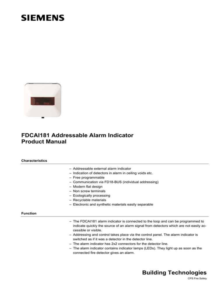
FDCAI181 Alarm indicator
advertisement

FDCAI181 Addressable Alarm Indicator Product Manual Characteristics – – – – – – – – – Addressable external alarm indicator Indication of detectors in alarm in ceiling voids etc. Free programmable Communication via FD18-BUS (individual addressing) Modern flat design Non screw terminals Ecologically processing Recyclable materials Electronic and synthetic materials easily separable Function – The FDCAI181 alarm indicator is connected to the loop and can be programmed to indicate quickly the source of an alarm signal from detectors which are not easily accessible or visible. – Addressing and control takes place via the control panel. The alarm indicator is switched as if it was a detector in the detector line. – The alarm indicator has 2x2 connectors for the detector line. – The alarm indicator contains indicator lamps (LEDs). They light up as soon as the connected fire detector gives an alarm. Building Technologies CPS Fire Safety Application – Indication of the alarm from detectors hidden from view. E.g. Ceiling voids, offices, store rooms etc. – For application in dry areas – Corridor indication of rooms covered by radio devices or over the door of monitored rooms FD18-BUS Addressable alarm indicator Installation 1 4 60 3 2 LED 56 Fig. 2 Fig. 1 Fig. 3 5 45 23. .5 21 16 5 40 14. .5 23 85 1 4. Fig. 4 Fig. 5 Fig. 6 WARNING Electrical voltage on lines Mortal danger due to electric shock During mounting and installation work, voltage must not be applied to the cables. 2 Building Technologies CPS Fire Safety LINE + LINE + LINE – 3.5 LINE – 56 85 32 Installation of FDCAI181: 1. Remove the white cover cap (press the black cam). 2. Mount the base plate (Fig. 2) on a wall or recess-mounted socket using 2 … 4 screws with max. diameter 3 mm. 3. Connect the alarm indicator in accordance with the connection diagram (Fig. 3, Fig. 6). 4. Refit the white cover cap. 5. Snap the white cover cap into place. Installation of additional frame AI330: For surface-mounted cable entry the additional frame AI330 must also be mounted. Max. cable diameter: 10 mm 1. Mount the additional frame AI330 (accessory) on a wall or recess-mounted socket using two screws with max. diameter of 4 mm (Fig. 4, Fig. 5). 2. Remove the white cover cap from alarm indicator FDCAI181 (press the black cam). 3. Attach the base plate of the alarm indicator to additional frame AI330 with 2 wood or sheet-metal screws of diameter 3 mm, max. 16 mm long. 4. Connect the alarm indicator in accordance with the connection diagram (Fig. 3, Fig. 6). 5. Refit the white cover cap. 6. Snap the white cover cap into place. Dimensions FDCAI181 AI330 16 85 85 32 85 85 Technical data Operating voltage Operating current (quiescent) Blinking cycle Load factor Connection terminals Operating temperature Storage temperature Humidity Communication protocol Color Protection category DC 12... 33 V <200µA 1s: Locate or Alarm 0.5s: Locate when Alarm 1 1.0…1.5 mm2 -10 ... +55 °C -20 ... +70 °C ≤95 % rel FD18-BUS white, ~RAL 9010 IP40 3 Siemens Building Technologies CPS Fire Safety Details for ordering Type FDCAI181 Part No. S54370-F21-A1 Beijing Siemens Cerberus Electronics Limited No.1,Fengzhidonglu, Xibeiwang, HaiDian District, Beijing, 100094, China Tel: +10 6476 8806 Fax: +10 6476 8899 Doc No. A6V10384005_a_en_-- Edition 09.2012 Designation Addressable alarm indicator Weight 0.0493 kg © Data and design subject to change without notice. Manual FD18 101237852


