ET-MWP100G
Multi Window Processor
Turnkey Solution for Multi Window Presentations
Unique Layout and Canvas Concept Adds
Impact to Multi-Screen Images
— Easy and Flexible Expandability with DIGITAL LINK Compatibility —
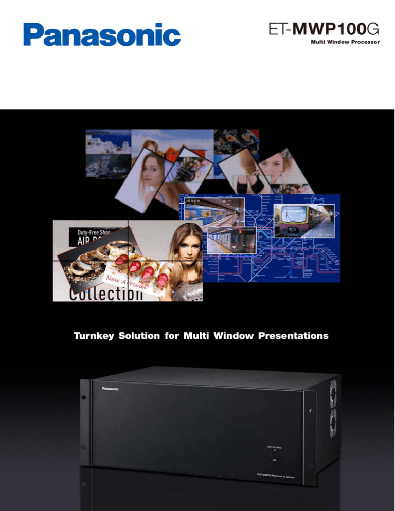
The ET-MWP100G Panasonic Multi Window Processor makes it possible to quickly and efficiently combine multiple projectors and flat
panel displays into a video wall or a multi vision system. Equipped
with 16 slots for input/output terminals, the ET-MWP100G enables a
combination of 5 optional interface boards, including a DIGITAL LINK
output board, to support a variety of input sources and output devices. Interface boards are also easy to add or change, making the
system highly flexible even after it has been configured. Images can
be split among multiple projectors or displays, and multi-windows
(PinP) can be freely allotted in desired sizes, locations, inclinations
and overlapping orders. Display patterns can be registered and
switched by control software for Multi Window Processor, which is
included with the ET-MWP100G, installed onto a PC. Even with interface boards mounted onto all 16 slots, the ET-MWP100G features
low power consumption of 160 W*1 or less, helping to lower the total
cost of ownership (TCO) in 24/7 continuous operation.
*1 When using a single power supply unit. The power consumption becomes
180 W when the optional ET-RPS100G power supply unit is added.
Layout and Canvas Concept
Layout
Defines how each output is used. Outputs
can be grouped together or used individually, and can be independently rotated
through 360° in real-time, without adding
additional delay, for use in creative video
wall applications. Multiple layouts can be
used at the same time or one layout can
be designed to tie multiple projectors or
displays together as one large image. Up
to 4 layouts can be used simultaneously.
Canvas
Designates how input images are output to
screens or displays. Multiple canvases can be
used at the same time to define multiple layouts to aid in choreographing a video design.
Up to 4 canvases can be stored to memory
and recalled anytime during operation, which
enables dynamic and impressive visual design.
Output image
Images are displayed
in the set windows.
Actual display units/projection
screens
From simple rectangles to complex formations, screens or display units can be
configured into a variety of combinations.
Window
Up to 36 windows can be used
to design a canvas with the
capability to resize and rotate
each window 360° on the canvas. The order in which windows
overlap can also be set.
How the Layout and Canvas Work
Input sources
Windows to show input images
Output on actual projection
screens or display units.
Layout simulates
the formation of
actual projection
screens or display
units.
Canvas designates how input images are output to
screens or displays. To output the maximum fullscreen area, the maximum canvas size is used.
Output Pattern Examples
A single image can be presented
across multiple displays. Window
layers can also be displayed.
Flat displays with different screen
sizes can be set as a single “canvas,”
and the image can be displayed at
the same scale throughout.
An integrated screen can combine projector screens
and displays.
Easy to Add or Replace Interface Boards.* 2 Lower Power Consumption.
Major ET-MWP100G Features
Dedicated “Control Software for Multi Window Processor” supplied
Single or multiple output layouts and multiple canvases
Simultaneous use of multiple layouts and canvases
20 presets for canvas setting
One or more windows (PinPs) on each canvas with 360° rotation
of each window
s 16 interface board slots
s Easy addition and replacement of optional interface boards*2
s Low power consumption of max 160 W*3 with 16 interface boards
mounted
s DIGITAL LINK compatibility (when the ET-MCQDL350 DIGITAL LINK
board mounted)
s Capability of up to 28 inputs with the ET-MCYDV100 DVI-U and
ET-MCYSD200 3G-SDI boards
s Up to 56 inputs with the ET-MCYSD210 HD-SDI board
s Capability of up to 28 outputs with the ET-MCQDV150 DVI-U and
ET-MCQDL350 DIGITAL LINK boards
s Bezel area adjustment capable for flat panel displays
s Edge Blending function for projectors
s
s
s
s
s
Optional interface board with 16 slots
Rear panel
ET-RPS100G Optional Power
Supply Unit
Built-in power supply unit
Network/serial control interface for the ET-MWP100G
* 2 Ask a qualified technician or your dealer when installing or removing this product.
* 3 When using a single power supply unit. The power consumption becomes 180 W when
the optional ET-RPS100G power supply unit is added.
NOTE: Photo shows the ET-MWP100G with optional interface boards and an
additional power supply unit mounted.
The ET-MWP100G Contributes to a Wide Variety of Multi-Screen Solutions
The ET-MWP100G Multi Window Processor can be used to build a wide range of creative, impressive images that were never before
possible, including video walls, digital signage, surveillance systems, TV studio displays, and live stage screens.
SOLUTION 1
Digital Signage Featuring TH-55LFV50 LED LCD Displays
Incorporating the ET-MWP100G into this system allows a variety of content to be displayed with a highly flexible layout. It
brings powerful impact and appeal to digital signage.
This video wall uses crisp, bright 55-inch LCD displays. The narrow
bezel makes the displayed images easy to see and understand.
TH-55LFV50
55
TH-55LFV50 Features
Large 55-inch LCD screen and high brightness of 800 cd/m2
makes the TH-55LFV50 ideal for installation in bright indoor places
s Super narrow bezel design for joints of only 5.3 mm (0.21˝ ) allows
seamless large-screen layouts
A tough and reliable design meets the demands for multi-screen
use
s Smart daisy-chain connection for easy operation
s
s
2
SOLUTION 2
Control Room Featuring PT-RZ475 SOLID SHINE Projectors
The low power consumption of the ET-MWP100G helps to
reduce the total cost of ownership (TCO). Reliability is also
increased by mounting the optional ET-RPS100G power supply
unit as a power backup. Combining this with the PT-RZ475 for
24/7 operation is recommended for surveillance or observation
use where high reliability is demanded.
This rear projection system uses projectors with an LED/Lasercombined light source to provide up to 10 years*4 of continuous
operation.
PT-RZ475
PT-RZ475 Features
Up to 10 years*4 (approximately 87,600 hours*5 ) of continuous
operation
s 24/7 operation
s DIGITAL LINK transmits digital signals up to 100 m (328 ft) with a
single CAT5e (STP) cable or higher
s
SOLUTION 3
s
s
3D projection and portrait mode capability
Powered-focus, short-throw lens
*4 With LIGHT POWER set to Eco2. Parts other than the light source may require replacement
in a shorter period.
*5 24 hours (1 day) × 365 days (1 Year) × 10 Years = 87,600 hours.
Broadcast Studio Featuring PT-DZ870 DLP™ Projectors
The ET-MWP100G’s optional interface boards support a wide
variety of input sources. This makes it possible to connect to
media servers, professional video cameras, and other devices. DIGTAL LINK compatibility also allows the input signals
from these devices to be output to the PT-DZ870 over a
single LAN cable*6.
This integrated system incorporates bright, high-quality edge
blended projection screens. Various image sources allow flexible
changes and display methods to match programming content.
PT-DZ870
PT-DZ870 Features
Bright 8,500 lm and high 10,000:1* 7 contrast ratio
Dynamic RGB Booster strikes a balance between brightness and
color reproduction
s Detail Clarity Processor 3 gives natural clarity to the finest details
s Edge blending, color matching and built-in multi-screen processor
for seamless mutli-screen projection
Geometric Adjustment and optional Geometry Manager Pro for
specially shaped screens
s DIGITAL LINK transmits digital signals up to 100 m (328 ft) with a
single CAT5e (STP) cable or higher
s
s
s
* 6 CAT5e (STP) cable or higher.
* 7 Full on/off, with dynamic iris on.
3
OTHER
SOLUTIONS
Staging and Events Featuring High-Brightness Projectors and Flat Panel Displays
Configuring a system with the ET-MWP100G enables flexible
combinations with a host of input devices and displays to
match applications like exhibitions, live staging, and video
conferences.
Fashion show
System Connection Example
Video wall
Rear projection multi-screen
*8
*8
*8
*8
Control PC
PC
Integrated projection / display system
Multi-screen projection system
Multi Window Processor
ET-MWP100G
PC
PC
PC
Camera
Teleconference
system
Professional
video camera
Blu-ray disc
player
Camera
Camera
Camera
Video Output
Video Input
L AN
* 8 Required to connect each output terminal of the ET-MWP100G with each projector or flat panel display. Up to 28 projectors can be simultaneously
output via DIGITAL LINK. This illustration is intended only to show display patterns. These patterns cannot all be simultaneously output.
Specifications
ET-MWP100G
Optional Interface Boards
ET-MCYDV100
Power supply
100−240 V AC, 50/60 Hz
Power consumption
160 W max. (180 W with the ET-RPS100G)
Board mounting slots
16 slots (including two dedicated input slots and two
dedicated output slots)
Scanning frequency
With the ET-MCYSD200
SDI
3G-SDI signal
With the ET-MCYSD200/MCYSD210
SDI
HD-SDI signal
SD-SDI signal
With the ET-MCYDV100
DVI-U (digital)
DVI-U (analog)/RGB
YP B P R (YC B C R )
Video/S-Video
Terminals
LAN
USB
3G-SDI
HD-SDI
SD-SDI
BNC × 2
SMPTE ST 424 compliant
SMPTE ST 292 compliant
SMPTE ST 259 compliant
HD-SDI
SD-SDI
BNC × 4
SMPTE ST 292 compliant
SMPTE ST 259 compliant
RGB
[YP B P R 4:2:2 10-bit] SMPTE ST 292 compliant:
750 (720)/60p, 750 (720)/50p, 1125 (1080)/60i,
1125 (1080)/50i, 1125 (1080)/25p, 1125 (1080)/24p,
1125 (1080)/30p
[YC BC R 4:2:2 10-bit] SMPTE ST 259 compliant:
525i (480i), 625i (576i)
SDI IN
ET-MCYSD210
SDI IN
ET-MCQDV150
DVI-U OUT
DVI-U 29-pin × 2
Digital
DVI 1.0 compliant, compatible with HDCP
RGB/YP B P R (YC B C R )
ET-MCQDL350
DIGITAL LINK OUT
LAN
482 × 177 × 313 mm
(18-31/32 × 6-31/32 × 12-5/16 in)
Weight* 3
Approx. 9.6 kg (21.16 lbs)
(when optional devices are mounted)
Operating environment
Operating temperature: 0 – 40 °C (32 –104 °F)* 4,
operating humidity: 10% – 85% (no condensation)
Supplied accessories
Power cord (× 3), software CD-ROM (Control Software
for Multi Window Processor)
ET-MWP100G Dimensions
YP B P R (YC B C R )
ET-MCYSD200
f H 15 .6 – 82.2 kHz, f V 24.0 – 85.1 Hz,
dot clock: 25 .2 –162 MHz
f H 15 .6 – 82.2 kHz, f V 24 – 85.1 Hz,
dot clock: 162 MHz or lower
525i (480i): f H 15.75 kHz; f V 60 Hz,
625i (576i): f H 15.63 kHz; f V 50 Hz,
525p (480p): f H 31.50 kHz; f V 60 Hz,
625p (576p): f H 31.25 kHz; f V 50 Hz,
750 (720)/60p: f H 45.00 kHz; f V 60 Hz,
750 (720)/50p: f H 37.50 kHz; f V 50 Hz,
1125 (1080)/60i: f H 33.75 kHz; f V 60 Hz,
1125 (1080)/50i: f H 28.13 kHz; f V 50 Hz,
1125 (1080)/25p: f H 28.13 kHz; f V 25 Hz,
1125 (1080)/24p: f H 27.00 kHz; f V 24 Hz,
1125 (1080)/30p: f H 33.75 kHz; f V 30 Hz,
1125 (1080)/60p: f H 67.50 kHz; f V 60 Hz,
1125 (1080)/50p: f H 56.25 kHz; f V 50 Hz
f H 15.75 kHz, f V 60 Hz [NTSC],
f H 15.63 kHz, f V 50 Hz [PAL]
Dimensions (W × H × D)
*1
*2
*3
*4
RJ-45 × 2
RJ-45 × 1 for network connection, 100Base-TX/10Base-T
Only compatible with dot clock frequency of 27 MHz (pixel repetition signal)
Compatible with VESA CVT-RB (Reduced Blanking) signals only
Average value. May differ depending on models.
At altitudes of 1,400 m (4,593 ft) or more, the operating temperature range is 0°C to
35°C (32°F to 95°F).
Options
ET-MCYDV100
DVI-U Board
s INPUTSFOR$6)5
ET-MCQDV150
DVI-U Board
s OUTPUTSFOR$6)5
ET-MCYSD200
3G-SDI Board
s INPUTSFOR'($3$3$)
ET-MCQDL350
DIGITAL LINK Board
s OUTPUTSFOR$)')4!,,).+
s !,!.CONNECTORJACKFORSERIAL
control and network connection
ET-MCYSD210
HD-SDI Interface Board
s INPUTSFOR($3$3$)
ET-RPS100G
Power Supply Unit
s !DDITIONALUNITFORBACKUP
unit: mm (inches)
4 36 (17-5 / 32 )
177 ( 6-31/ 32 )
29 4 (11-9 /16 )
313 (12-5 /16 )
S-Video
Video
DVI-U 29-pin × 2
DVI 1.0 compliant, compatible with HDCP,
for single link only
525i (480i),* 1 625i (576i),* 1 525p (480p), 625p (576p),
750 (720)/60p, 750 (720)50p, 1125 (1080)/60i,
1125 (1080)/50i, 1125 (1080)/25p, 1125 (1080)/24p,
1125 (1080)/30p, 1125 (1080)/60p, 1125 (1080)/50p,
VGA (640 × 480)–WUXGA* 2 (1,920 × 1,200), compatible
with non-interlaced signals only, dot clock: 25 –162 MHz
R, B: 0.7 Vp-p, G: 0.7 Vp-p (1.0 Vp-p for sync on G), 75 ohms
HD, VD/SYNC: TTL, high impedance, positive/negative
automatic
Y: 1.0 Vp-p (including sync signal), P B /P R (C B /C R ):
0.7 Vp-p, 75 ohms
Y: 1.0 Vp-p, C: 0.286 Vp-p, 75 ohms
Y: 1.0 Vp-p, 75 ohms
Digital
[Level A YP BP R 4:2:2 10-bit] SMPTE ST 424 compliant:
1125 (1080)/60p, 1125 (1080)/50p
D-sub 9-pin (female) × 1 for external control
(RS-232C compliant)
RJ-45 × 1 for external control, 100Base-TX/10Base-T
Type A × 1 (front), Type B × 1 (rear), for service
SERIAL IN
DVI-U IN
4 82 (18-31/ 32 )
NOTES ON USE
1. Do not install the E T-MWP100G in locations that are subject to excessive water, humidity,
steam, or oily smoke. Doing so may result in fire, malfunction, or electric shock.
2. Never place objects on top of the E T-MWP100G while it is operation.
For more information about Panasonic projectors, please visit:
Projector Global Web Site – panasonic.net/avc/projector
Facebook – www.facebook.com/panasonicprojector
YouTube – www.youtube.com/user/PanasonicProjector
Weights and dimensions shown are approximate. Specifications and appearance are subject to
change without notice. Product availability differs depending on region and country. This product
may be subject to export control regulations. DLP is a trademark or a registered trademark of
Texas Instruments. For more detailed information, please consult the dealer from whom you are
purchasing the product. All other trademarks are the property of their respective trademark
owners. Projection images simulated. © 2013 Panasonic Corporation. All rights reserved.
All information included here is valid as of July 2013.
ET-MWP100G1 Printed in Japan.

