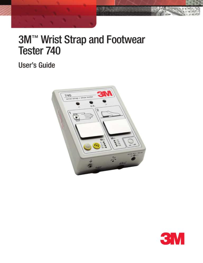
3M™ Wrist Strap and Footwear
Tester 740
User’s Guide
Table of Contents
Section Page
Safety Information.................................................................................................3
1.0General..........................................................................................................4
2.0Description....................................................................................................4
3.0Operation.......................................................................................................5
4.0 Wall Mounting..............................................................................................5
5.0 Wrist Strap Test.............................................................................................6
6.0 Shoe Test.......................................................................................................7
7.0 Data Output Connector.................................................................................8
8.0Specifications................................................................................................9
9.0 Calibration Procedure.................................................................................10
10.0Logbook......................................................................................................11
Regulatory Information........................................................................................12
Warranty...............................................................................................................13
2
SAFETY INFORMATION
Explanation of Signal Word Consequences
WARNING
Indicates a potentially hazardous situation which, if not avoided, could
result in death or serious injury and/or property damage.
CAUTION
Indicates a potentially hazardous situation which, if not avoided, may
result in minor or moderate injury and/or property damage.
NOTICE
Indicates a potentially hazardous situation, which, if not avoided, may result
in property damage.
WARNING
To reduce the risks associated with environmental contamination:
•• When working with the automated equipment, always observe safety precautions as recommended by
equipment manufacturer and your company’s practices.
CAUTION
To reduce the risks associated with environmental contamination:
•• Dispose of the monitor in accordance with local, state, and federal regulations.
NOTICE
To reduce the risks associated with property damage:
•• Periodically check that the indicator is functioning properly.
3
740
wrist strap + shoe tester
LED for
«too low resistance»
<
LED for
«too high resistance»
>
o.k.
1
2
Contact plate
for shoe test
Ground cord
4 mm stud
Contact plate for
wrist strap test
2
5
10
35
Socket for
wrist strap
MΩ
Output
- 10
- 35
- 50
- 100
R
max
on / off
DC 24•30 V / 150 mA
+
Ground socket
Output signal for external devices
e.g. - data transfer to PC, electrical door
opening system, acoustic signal, etc.
On / Off switch
MΩ
-
-
Connection for AC/DC
transformer
LED
Socket for
Upper limit
selection for wrist shoe electrode
strap and shoe test
1.0General
Personnel grounding devices such as wrist straps and conductive footwear are
the primary method to minimize charge generation on the human body. They
must be able to drain this charge as rapidly as it is generated. For this reason,
it is important to test wrist straps and conductive footwear on a regular basis to
ensure they are functioning properly and that the test results can be recorded.
2.0Description
The 3M™ Wrist Strap and Footwear Tester 740 is an electronic test instrument that
is easy to operate and is designed to be wall-mounted. An AC/DC transformer is
supplied. The Wrist Strap and Footwear Tester 740 switches off automatically after
non-use for approximately 30 minutes.
The unit consists of two measurement circuits with an open circuit test voltage of
14V for wrist strap and shoe test applications. For wrist strap and footwear testing,
4
a minimum threshold resistance of 750 kΩ is set internally. The desired maximum
allowable resistance level can be selected separately for each measurement. If the
resistance of the tested wrist strap or footwear is within the selected range, the
green “o.k.”- LED will illuminate. The red “>” - LED alerts the operator that the
resistance of the tested device is under 750 kΩ. The red “>”- LED indicates that
the selected maximum resistance is exceeded.
The 3M™ Wrist Strap and Footwear Tester 740 can be connected to external
devices such as computers (for data recording), electrical door opening systems,
or other logic driven components.
The Wrist Strap and Footwear Tester 740 consists of:
• Base unit
• Data output connector plug
• Wall mounting kit, 3M™ Dual Lock™ Fastening System and template
• Cover for wrist strap plug-in jack
• AC/DC transformer
• Ground cord
Accessories:
3M™ Shoe Electrode 741 (to be ordered separately)
3.0Operation
Connect the AC/DC transformer (24-30VDC, 150mA) to the Wrist
Strap and Footwear Tester 740.
Note: If you notice a delay in the response time of the LED illumination please connect
the ground cord supplied to the ground socket of the Wrist Strap and Footwear Tester.
Please ensure proper earth ground connection!
Switch the unit on. All LEDs will flash for approximately 1 second
to check their function. Select the desired upper maximum resistance
level for both the wrist strap and shoe test by using a small screw
driver.
The Shoe Electrode 741 must be connected if footwear testing is
required.
4.0Wall Mounting
The enclosed 3M™ Dual Lock™ Fastening Discs must be screwed to the wall
using the attached template approximately 1.5 m (5 feet) above the floor. Drill
three holes of 5 mm (0.2 in.) diameter at marked locations. Make sure the area
on the Wrist Strap and Footwear Tester 740 in which the Dual Lock Fastening
5
Strips are placed is free of dust and dirt. Attach the 3M™ Dual Lock™ Fastening
Strips to the rear of the 3M™ Wrist Strap and Footwear Tester 740 to the bottom
and top in parallel; see drawing for locations.
For securing on the wall, press the Wrist Strap and Footwear Tester 740 firmly
against the discs. For removal of the Wrist Strap and Footwear Tester 740, lift the
top corners with both hands.
3M™ Wrist Strap
and Footwear
Tester 740
1.5 m
(5 feet)
5.0Wrist Strap Test
Put the wrist band on with ground cord attached and insert the ground cord into
the wrist strap plug-in jack. Depress the metal contact plate and hold it. One of
the indicator-LEDs will illuminate.
An illuminated green LED indicates that
the wrist strap performs within the resistance range of 750 kΩ to the upper
selected value of 2, 5, 10 or 35 MΩ. If a red “< “-LED is on, the current limiting
resistor in the ground cord is bypassed and the cord has to be replaced. The red
“> “-LED indicates that the selected resistance range is exceeded. Check to see
if the high resistance is in the cord, the wrist band or in the contact between
wrist band and the operator’s skin. To check the resistance of the ground cord,
leave the plug end of the ground cord attached to the tester and disconnect the
snap end from the wrist band. Connect ground cord snap to the stud in the hand
symbol or press it onto the contact plate and depress the plate until one of the
LEDs is illuminated.
If the green LED illuminates now, the ground cord can be
used.
If the red “> “- LED is lit, replace the ground cord.
In some cases, high contact resistance between the skin
and wrist band will cause the tester to show a red “>” LED condition. This resistance may be caused by dry skin
6
or the presence of hair in the wrist area. The use of a skin lotion is recommended
to solve this problem.
If a red “>”- LED condition still exists, replace the wrist band. or the presence
of hair in the wrist area. The use of a skin lotion is recommended to solve this
problem.
If a red “>”- LED condition still exists, replace the wrist band.
6.0Shoe test
The 3M™ Shoe Electrode 741 must be connected to the 3M™ Wrist Strap and
Footwear Tester 740 shoe jack.
Switch the Wrist Strap and Footwear Tester 740 on. Stand on
the applied shoe electrode. If you are using shoe straps with a
1 MΩ resistor on both feet to be tested with the 741, you have
to test the straps one after the other, to avoid a red “too low”
- indication. Care must be taken not to put the non-tested foot
on ESD - protective flooring to avoid a bypass to ground. Press
the metal contact plate for shoe test until one of the indicator LEDs lights up. The green LED indicates that the resistance of
the person through the footwear is in the range between 750 kΩ
and the desired upper maximum level (10, 35, 50 or 100 MΩ).
7
7.0 Data Output Connector
If you are going to use the data output connector you must follow a test
sequence. Test the wrist strap first and then the shoe. If this sequence is not
strictly kept, the output at the pins described on page 9 will be incorrect.
The 3M™ Wrist Strap and Footwear Tester 740 will provide digital signals (high/
low) while testing the personnel grounding devices. These digital signals can be
used for data recording (Example 1) and authorization control equipment such
as electrical door opening systems (Example 2). The output of the Wrist Strap
and Footwear Tester 740 will give you permanently + 5V at pin 3 and DC-return
at pin 6. The remaining pins 1, 2, 4 and 5 (open collector) will be high (max. +
30V/20mA have to be provided externally) or low (DC-return) while pressing on
the contact plates either for wrist strap or shoe tests. The chart on page 9 shows
all of the possible test results and the corresponding output levels.
Example 1: Output connection for
use with a computer
Example 2: Output connection for use
with a controlling device
8
Data output connector pin status when testing wrist strap/shoe
The sequence for testing must be wrist strap test first and then the shoe test.
Shaded pin indicators will read “hi” if the sequence is reversed or
only the shoe tests are performed.
Data Output Connector
pin 1, 2, 4, 5 - high or low
pin 3 - +5V
pin 6 - DC-return
8.0 Specifications
Dimension of base unit
14 cm W x 5.5 cm H x 19 cm L
(5.5" W x 2.14" H x 7.5" L)
Weight
15.5 ozs. (438 g)
Power supply
External AC/DC transformer,
24-30VDC/150mA
Accuracy
± 10% of 2, 5, 10, 35 and 50 MΩ-ranges
± 20% of 100 MΩ-range
Output
Open collector at pin 1,2, 4, 5
(max. 30V/20 mA)
DC-return at pin 6, + 5V at pin 3
Voltage
14VDC (open circuit)
9
9.0 Calibration Procedure
The following procedure can be used to determine if the 3M™ Wrist Strap and
Footwear Tester 740 operates within its specifications.
Please note: The tester has no adjustable components.
Equipment needed:
Resistors: 750 kΩ - 120 MΩ, tolerance ± 1%
740
wrist strap + shoe tester
2 leads: as required to connect the reference resistor
<
Calibration of wrist strap test circuit
Connect the reference resistor to the Wrist Strap and
Footwear Tester 740 as shown in the figure below.
Switch the Wrist Strap and Footwear Tester 740 unit
on. Select the 2 MΩ-range and use the reference
resistors as indicated in the test table and press
contact plate A.
>
o.k.
1
2
MΩ
MΩ
2 5 10 35 -
Output
- 10
- 35
- 50
- 100
on / off
R
max
DC 24•30 V / 150 mA
+
-
The LEDs will indicate as shown below if the Wrist Strap and Footwear Tester
740 performs within specifications. Repeat this procedure for 5, 10 and 35 MΩranges.
Reference Resistor
Resistance Range Settings
LED Indication
750 kΩ
900 kΩ
1.8 MΩ
> 2.2 MΩ
2 MΩ - range
Red
Green
Green
Red
4.5 MΩ
> 5.5 MΩ
5 MΩ - range
Green
Red
9.0 MΩ
> 11.0 MΩ
10 MΩ - range
Green
Red
31.5 MΩ
> 38.5 MΩ
35 MΩ - range
Green
Red
*
* The 750 kΩ threshold is approximate for that range and could vary slightly. Actual threshold resistances are not listed.
10
3M™ Wrist Strap and Footwear Tester 740 Logbook
Month / Year
1 2 3 4 5 6 7 8 9 10 11 12 13 14 15 16 17 18 19 20 21 22 23 24 25 26 27 28 29 30 31
Name
W S W S W S W S W S W S W S W S W S W S W S W S W S W S W S W S W S W S W S W S W S W S W S W S W S W S W S W S W S W S W S
Test 1
Test 2
Test 1
Test 2
Test 1
Test 2
Test 1
Test 2
Test 1
Test 2
Test 1
Test 2
Test 1
Test 2
Test 1
Test 2
Test 1
Test 2
Test 1
Test 2
Test 1
Test 2
Test 1
Test 2
Test 1
Test 2
Test 1
Test 2
Test 1
Test 2
Test 1
Test 2
Test 1
Test 2
Unit calibrated on:
Example:
Test parameters:
Not ok:
Wrist Strap (W)
Shoes (S)
750 kΩ to: 2 MΩ
750 kΩ to: 10 MΩ
x
ok:
Month / Year
Name
1 2 3 4
W S W S W S W S
Test 1 x x x x x x
Test 2 x x x x
x
5 MΩ
35 MΩ
10 MΩ
50 MΩ
35 MΩ
100 MΩ
11
By:
Next calibration on:
Serial number:
Regulatory Information
To reduce the risks associated with environmental contamination from the
device: At the end of service life, dispose of the unit in accordance with federal,
state and local requirements.
WEEE Statement
The following information is only for EU-members States: The mark shown
to the right is in compliance with Waste Electrical and Electronic Equipment
Directive 2002/96/EC (WEEE). The mark indicates the requirement NOT to
dispose the equipment as unsorted municipal waste, but use the return and
collection systems according to local law.
12
3M and Dual Lock are trademarks of 3M Company.
Important Notice
All statements, technical information, and recommendations related to 3M’s products
are based on information believed to be reliable, but the accuracy or completeness is
not guaranteed. Before using this product, you must evaluate it and determine if it is
suitable for your intended application. You assume all risks and liability associated with
such use. Any statements related to the product which are not contained in 3M’s current
publications, or any contrary statements contained on your purchase order shall have no
force or effect unless expressly agreed upon, in writing, by an authorized officer of 3M.
Warranty; Limited Remedy; Limited Liability.
This product will be free from defects in material and manufacture for one year from
the time of purchase. 3M MAKES NO OTHER WARRANTIES INCLUDING, BUT
NOT LIMITED TO, ANY IMPLIED WARRANTY OF MERCHANTABILITY
OR FITNESS FOR A PARTICULAR PURPOSE. If this product is defective within
the warranty period stated above, your exclusive remedy shall be, at 3M’s option, to
replace or repair the 3M product or refund the purchase price of the 3M product. Except
where prohibited by law, 3M will not be liable for any indirect, special, incidental or
consequential loss or damage arising from this 3M product, regardless of the legal
theory asserted.
3
Electronics Materials Solutions Division
Static Control Products
926 JR Industrial Drive
Sanford, NC 27332-9733
Toll-Free: 866-722-3736
International: 919-718-0000
Email: 3mstaticinfo@mmm.com
www.3Mstatic.com
Please recycle. Printed in USA.
© 3M 2014. All rights reserved.
78-9100-6761-6B JHA


