Section 040–001–002
Charles Industries, Ltd.
Third Printing, March 1999
Type 400 Mounting Shelves
CONTENTS
Part 1.
Part 2.
Part 3.
Part 4.
Part 5.
Part 6.
PAGE
GENERAL . . . . . . . . . . . . . . . . . . . . . . . . . . . . . . . . . . . . . . . . . . . . . . . . . . . . . . . . . . . . . . . . . . . . . . . . . . . . .
INSPECTION . . . . . . . . . . . . . . . . . . . . . . . . . . . . . . . . . . . . . . . . . . . . . . . . . . . . . . . . . . . . . . . . . . . . . . . . . . .
MOUNTING . . . . . . . . . . . . . . . . . . . . . . . . . . . . . . . . . . . . . . . . . . . . . . . . . . . . . . . . . . . . . . . . . . . . . . . . . . . .
TECHNICAL ASSISTANCE . . . . . . . . . . . . . . . . . . . . . . . . . . . . . . . . . . . . . . . . . . . . . . . . . . . . . . . . . . . . . .
WARRANTY & CUSTOMER SERVICE . . . . . . . . . . . . . . . . . . . . . . . . . . . . . . . . . . . . . . . . . . . . . . . . . . . .
SPECIFICATIONS . . . . . . . . . . . . . . . . . . . . . . . . . . . . . . . . . . . . . . . . . . . . . . . . . . . . . . . . . . . . . . . . . . . . . .
2
2
3
4
4
6
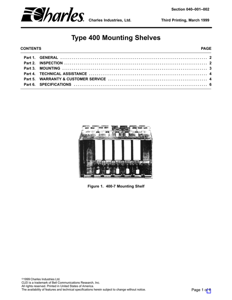
Figure 1. 400-7 Mounting Shelf
e1999 Charles Industries Ltd.
CLEI is a trademark of Bell Communications Research, Inc.
All rights reserved. Printed in United States of America.
The availability of features and technical specifications herein subject to change without notice.
Page 1 of 6
Section 040–001–002
1.
GENERAL
1.1
Document Purpose
This document provides a description of the Charles Industries Type 400 Mounting Shelves; Equipment Issues
(400–1 to 5, Equipment Issue 2; 400–6 to 13, Equipment Issue 3; 400–11FM, Equipment Issue 1). The 400–7
Mounting Shelf is shown in Figure 1. The capacities of the mounting shelves range from one module to 13 modules which make electrical connection to associated equipment through bifurcated contacts of 56-pin, wire-wrap,
connectors at the rear of the mounting shelf. Figure 2 shows one of these connectors and the pin assignments,
which are stenciled on the sides of each connector. In a 400–XX Mounting Shelf, the XX refers to the number of
card positions.
1.2
Document Status
This document is reprinted to include a general editorial update.
1.3
Equipment Purpose/ Description
The Charles Industries Type 400 Mounting Shelves provide relay rack or KTU apparatus case mounting for all
400-type Charles Industries modules. Shelves are of cast aluminum and are equipped with top and bottom
mounting brackets for KTU mounting or side ears for relay rack mounting.
All Charles Industries Type 400 mounting shelves are expandable with the exception of the 400–11 and 400–13,
which utilize solid one-piece top and bottom construction. The 400–11 FM is an eleven-slot shelf which is also
expandable.
2.
INSPECTION
Inspect the equipment thoroughly as soon as possible after delivery. If the equipment has been damaged in transit, immediately report the extent of damage to the transportation company.
Charles Industries equipment is identified by a model and issue number imprinted on the front panel or located
elsewhere on the equipment. Each time a major engineering design change is made on the equipment, the issue
number is advanced by one number on any following models that are manufactured. Therefore, be sure to include
the issue number along with the model number when making inquiries about the equipment.
Figure 2. Type 400 56-Pin Connector
2
Section 040-001-002
Figure 3. 400–1 Shelf Assembly
3.
MOUNTING
3.1
Rack Mounting
The 400–1 through 400–9 Mounting Shelves are equipped with top and bottom brackets (Figure 3 illustrates the
400–1) and require mounting bars for installation on a 19-inch or 23-inch relay rack. The mounting bars must be
ordered separately. (See Note 4 of Table 1.) The mounting bars when required are ordered under the following
part numbers:
(a) Model No. 892 9 for 19-inch mounting kit.
(b) Model No. 8923–23 for 23-inch mounting kit.
The 400–10 and 400–11 Mounting Shelves are equipped with mounting ears for mounting directly on 19-inch
relay racks. The 400–12 and 400–13 Mounting Shelves are similarly equipped for mounting on a 23-inch relay
rack.
When 400–1 through 400–9 Mounting Shelves are installed with mounting bars, seven inches of vertical space
(four mounting spaces) are required. The 400–10 through 400–13 Mounting Shelves require only six inches of
vertical rack space. Extensions for the mounting of 400–10 and 400–11 on 23-inch racks may be ordered separately. Install the shelves with mounting screws provided.
3.2
Flush Mounting
All Type 400 Mounting Shelves may be flush mounted with the exception of the 400–11. The 400–11 FM is a specially designed shelf with factory drilled holes and is used exclusively for flush mounting. See Figure 4. Flush
mounting for other shelves is a non-standard mounting, and, as such, must have holes drilled and tapped. The
reversed mounting ear is used as a template for hole location.
3.3
Case Mounting
Type 400–1 (one-module) through 400–6 (six modules) Mounting Shelves may be installed in a 15A (equivalent to
WESTERN ELECTRIC 31 B) KTU apparatus case. Type 400–1 through 400–13 Mounting Shelves may be
installed in a 16C (equivalent to WESTERN ELECTRIC 16C) KTU apparatus case.
3
Section 040–001–002
Figure 4. 400-11FM (Flush Mounted) Shelf Assembly
4.
TECHNICAL ASSISTANCE
4.1
Technical Assistance — U.S.
If technical assistance is required, contact Charles Industries’ Technical Services Center at:
847–806–8500
847–806–8556 (FAX)
800–607–8500
techserv@charlesindustries.com (e-mail)
4.2
Technical Assistance — Canada
Canadian customers contact:
905–821–7673 (Main Office)
905–821–3280 (FAX)
5.
WARRANTY & CUSTOMER SERVICE
5.1
Warranty
Charles Industries, Ltd. offers an industry-leading, 5-year warranty on products manufactured by Charles Industries. Contact your local Sales Representative at the address or telephone numbers below for warranty details.
The warranty provisions are subject to change without notice. The terms and conditions applicable to any specific
sale of product shall be defined in the resulting sales contract.
Charles Industries, Ltd.
5600 Apollo Drive
Rolling Meadows, Illinois 60008–4049
Telephone:
4
847–806–6300 (Main Office)
847–806–6231 (FAX)
Section 040-001-002
5.2
Field Repairs (In-Warranty Units)
Field repairs involving the replacement of components within a unit are not recommended and may void the warranty and compatibility with any applicable regulatory or agency requirements. If a unit needs repair, contact
Charles Industries, Ltd. for replacement or repair instructions, or follow the Repair Service Procedure below.
5.3
Advanced Replacement Service (In-Warranty Units)
Charles Industries, Ltd. offers an “advanced replacement” service if a replacement unit is required as soon as
possible. With this service, the unit will be shipped in the fastest manner consistent with the urgency of the situation. In most cases, there are no charges for in-warranty repairs, except for the transportation charges of the unit
and for a testing and handling charge for units returned with no trouble found. Upon receipt of the advanced replacement unit, return the out-of-service unit in the carton in which the replacement was shipped, using the preaddressed shipping label provided. Call your customer service representative at the telephone number above for
more details.
5.4
Standard Repair and Replacement Service (Both In-Warranty and Out-Of-Warranty Units)
Charles Industries, Ltd. offers a standard repair or exchange service for units either in- or out-of-warranty. With
this service, units may be shipped to Charles Industries for either repair and quality testing or exchanged for a
replacement unit, as determined by Charles Industries. Follow the Repair Service Procedure below to return units
and to secure a repair or replacement. A handling charge applies for equipment returned with no trouble found. To
obtain more details of this service and a schedule of prices, contact the CI Service Center at 217–932–5288 (FAX
217–932–2943).
Repair Service Procedure
1. Prepare, complete, and enclose a purchase order in the box with the equipment to be returned.
2. Include the following information:
– Company name and address
– Contact name and phone number
– Inventory of equipment being shipped
– Particulars as to the nature of the failure
– Return shipping address
3. Ship the equipment, purchase order, and above-listed information, transportation prepaid, to the service center address shown below.
CI Service Center
Route 40 East
Casey, IL 62420–2054
4. Most repaired or replaced units will be returned within 30 or 45 days, depending on the product type
and availability of repair parts. Repaired units are warranted for either 90 days from the date of repair
or for the remaining unexpired portion of the original warranty, whichever is longer.
5
Section 040–001–002
6.
SPECIFICATIONS
Specifications for the physical characteristics of Charles Industries Type 400 Mounting Shelves are provided in
Table 1.
Table 1. Type 400 Mounting Shelf Specifications
DIMENSIONS IN INCHES
MODEL NO.
400-1
400-2
400-3
400-4
400-5
MODULE
CAPACITY
1
2
3
4
5
400-6
6
7.0
400-7
400-8
400-9
400-10
400-11
7
8
9
10
11
7.0
7.0
7.0
5.9
5.9
400-11FM
400-12
11
12
5.9
5.9
400-13
13
5.9
MOUNTING
KTU
(See notes 3
and 4)
19” rack
(See notes 5
and 7)
23” rack (See
note 6)
HEIGHT
WIDTH
DEPTH
7.0
7.0
7.0
7.0
7.0
1.9
3.4
4.9
6.4
8.0
7.2
7.2
7.2
7.2
7.2
WEIGHT
(POUNDS)
1.6
2.2
2.8
3.4
4.0
9.5
7.2
4.7
11.1
12.6
14.1
19.0
19.0
7.2
7.2
7.2
7.2
7.2
5.4
6.1
6.8
7.5
8.2
19.0
23.1
7.2
7.2
8.2
9.1
23.1
7.2
9.7
Notes:
1. All installer connections are made to 56-pin, wire-wrap connectors provided as part of the mounting assembly.
2. Factory wiring can be provided when required.
3. Overall height of 400-1 through 400-9 includes top and bottom mounting brackets punched for standard KTU/
KTS mounting bars.
4. When mounting 400-1 through 400-9 on a relay rack, order one 8923-19 Mounting Kit for 19” racks, or one
8923-23 Mounting Kit for 23” racks.
5. Overall width includes mounting brackets for 19” racks drilled on 1 3/4 inch centers.
6. Overall width includes mounting brackets for 23” racks drilled on 2 inch centers.
7. Order 8982-03 Kit for mounting 19” mounting assembly on 23” rack.
g g g
6

