APPLICATION NOTE
Multi-layer Slow Blow Fuses
Help Protect Automotive Infotainment
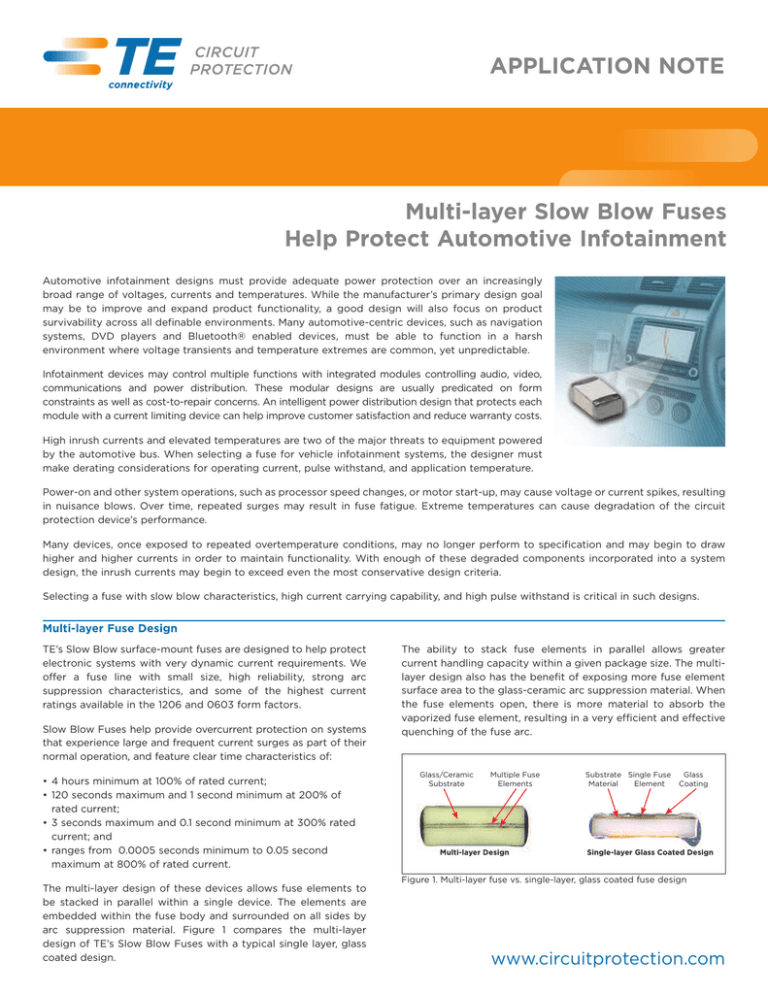
Automotive infotainment designs must provide adequate power protection over an increasingly
broad range of voltages, currents and temperatures. While the manufacturer’s primary design goal
may be to improve and expand product functionality, a good design will also focus on product
survivability across all definable environments. Many automotive-centric devices, such as navigation
systems, DVD players and Bluetooth® enabled devices, must be able to function in a harsh
environment where voltage transients and temperature extremes are common, yet unpredictable.
Infotainment devices may control multiple functions with integrated modules controlling audio, video,
communications and power distribution. These modular designs are usually predicated on form
constraints as well as cost-to-repair concerns. An intelligent power distribution design that protects each
module with a current limiting device can help improve customer satisfaction and reduce warranty costs.
High inrush currents and elevated temperatures are two of the major threats to equipment powered
by the automotive bus. When selecting a fuse for vehicle infotainment systems, the designer must
make derating considerations for operating current, pulse withstand, and application temperature.
Power-on and other system operations, such as processor speed changes, or motor start-up, may cause voltage or current spikes, resulting
in nuisance blows. Over time, repeated surges may result in fuse fatigue. Extreme temperatures can cause degradation of the circuit
protection device’s performance.
Many devices, once exposed to repeated overtemperature conditions, may no longer perform to specification and may begin to draw
higher and higher currents in order to maintain functionality. With enough of these degraded components incorporated into a system
design, the inrush currents may begin to exceed even the most conservative design criteria.
Selecting a fuse with slow blow characteristics, high current carrying capability, and high pulse withstand is critical in such designs.
Multi-layer Fuse Design
TE’s Slow Blow surface-mount fuses are designed to help protect
electronic systems with very dynamic current requirements. We
offer a fuse line with small size, high reliability, strong arc
suppression characteristics, and some of the highest current
ratings available in the 1206 and 0603 form factors.
Slow Blow Fuses help provide overcurrent protection on systems
that experience large and frequent current surges as part of their
normal operation, and feature clear time characteristics of:
• 4 hours minimum at 100% of rated current;
• 120 seconds maximum and 1 second minimum at 200% of
rated current;
• 3 seconds maximum and 0.1 second minimum at 300% rated
current; and
• ranges from 0.0005 seconds minimum to 0.05 second
maximum at 800% of rated current.
The ability to stack fuse elements in parallel allows greater
current handling capacity within a given package size. The multilayer design also has the benefit of exposing more fuse element
surface area to the glass-ceramic arc suppression material. When
the fuse elements open, there is more material to absorb the
vaporized fuse element, resulting in a very efficient and effective
quenching of the fuse arc.
Glass/Ceramic
Substrate
Multiple Fuse
Elements
Multi-layer Design
Substrate Single Fuse
Material
Element
Glass
Coating
Single-layer Glass Coated Design
Figure 1. Multi-layer fuse vs. single-layer, glass coated fuse design
The multi-layer design of these devices allows fuse elements to
be stacked in parallel within a single device. The elements are
embedded within the fuse body and surrounded on all sides by
arc suppression material. Figure 1 compares the multi-layer
design of TE’s Slow Blow Fuses with a typical single layer, glass
coated design.
www.circuitprotection.com
Temperature Derating
A fuse is a temperature sensitive device. Therefore, operating temperature will have an effect on fuse performance and lifetime. Operating
temperature should be taken into consideration when selecting the fuse current rating.
The minimum fuse current rating selection is determined by the
following formula:
Ifuse ≥ (Isys/0.75)/Ktemp
Where:
Themal Derating Curve
% of Carrying Current Capacity
Thermal derating curves can be used to determine the derating
percentage based on operating temperature. Figure 2 shows the
thermal derating curve for TE’s Slow Blow Fuses.
110
100
90
80
88%
70
60
50
40
30
20
10
0
-55 -45 -35 -25 -15
Ktemp is the temperature derating factor
-5
5
15
25
35 45 55
65 70
85 95 105 115 125
Maximum Operating Temperature (˚C)
Figure 2. TE’s Slow Blow Fuse Thermal Derating Curve
Transient State or Pulse Derating
These pulses have an effect on the fuse element because the
transient heating they induce causes thermal cycling within the
device. Pulses can affect the life of the fuse. Therefore, the pulse
energy and the number of times the fuse may be subjected to the
pulses must be considered.
The I2t parameter provides a measure of the fuse’s ability to
withstand the energy of a pulse. By determining the I2t energy of
the pulse, it can be compared to the fuse’s I2t curve to determine
what the rated current of the fuse must be to help ensure reliable
fuse performance.
Once the I2t value for the application waveform has been
determined, the device must be derated based on the thermal
environment and the number of cycles expected over the
system lifetime. Since the stress induced by the current pulse
is cumulative in nature, the number of times the stress is
applied has significant bearing on how much derating must
be applied to the fuse rating. Figure 3 presents the current
pulse-derating curve for TE’s surface mount chip fuses up to
100,000 cycles.
TE’s Slow Blow Fuse provides some of the highest current ratings
available in the 1206 and 0603 footprints and enhances hightemperature performance in a wide range of circuit protection
designs. Each power circuit within a modular automotive
infotainment system can be individually protected with a single
device. The RoHS-compliant device is designed for operating
temperatures between –55°C and +125°C, and withstands
soldering temperatures of up to 260°C for 60 seconds maximum.
To determine the specific TE 1206SFS or 0603SFS Slow
Blow
Fuse
for
your
application,
please
refer
to
http://circuitprotection.com/slowblow.asp for the latest product
information and Fuse Selection Guide.
Pulse Derating Curve
100%
% of Minimum I2t
The term “pulse” is used to describe any type of transient current
that may be applied to the fuse. Common examples of pulses are
inrush currents observed at system power-on, motor start-up
currents and more extended duration peak currents observed
during high-speed processing activity in computing systems.
10%
100
1000
10,000
Number of Pulses
Figure 3. TE’s Slow Blow Fuse Pulse Derating Curve
Bluetooth is a trademark of Bluetooth SIG, Inc.
TE Circuit Protection
308 Constitution Drive
Menlo Park, CA USA 94025-1164
Tel : (800) 227-7040, (650) 361-6900
Fax : (650) 361-4600
www.circuitprotection.com
www.circuitprotection.com.hk (Chinese)
www.te.com/japan/bu/circuitprotection (Japanese)
TE Connectivity, TE connectivity (Logo) and TE (logo) are trademarks of the TE Connectivity Ltd. family of companies. Other
logos, product and company names mentioned herein may be trademarks of their respective owners. All information, including
illustrations, is believed to be accurate and reliable. However, users should independently evaluate the suitability of each product
for their application. Tyco Electronics Corporation and/or its Affiliates in the TE Connectivity Ltd. family of companies (“TE”) makes
no warranties as to the accuracy or completeness of the information, and disclaims any liability regarding its use. TE’s only
obligations are those in the TE Standard Terms and Conditions of Sale and in no case will TE be liable for any incidental, indirect,
or consequential damages arising from the sale, resale, use, or misuse of the product. Specifications are subject to change without
notice. In addition, TE reserves the right to make changes without notification to Buyer — to materials or processing that do not
affect compliance with any applicable specification.
©2014 Tyco Electronics Corporation, a TE Connectivity Ltd. company. All rights reserved. RCP0025E.0414
100,000


