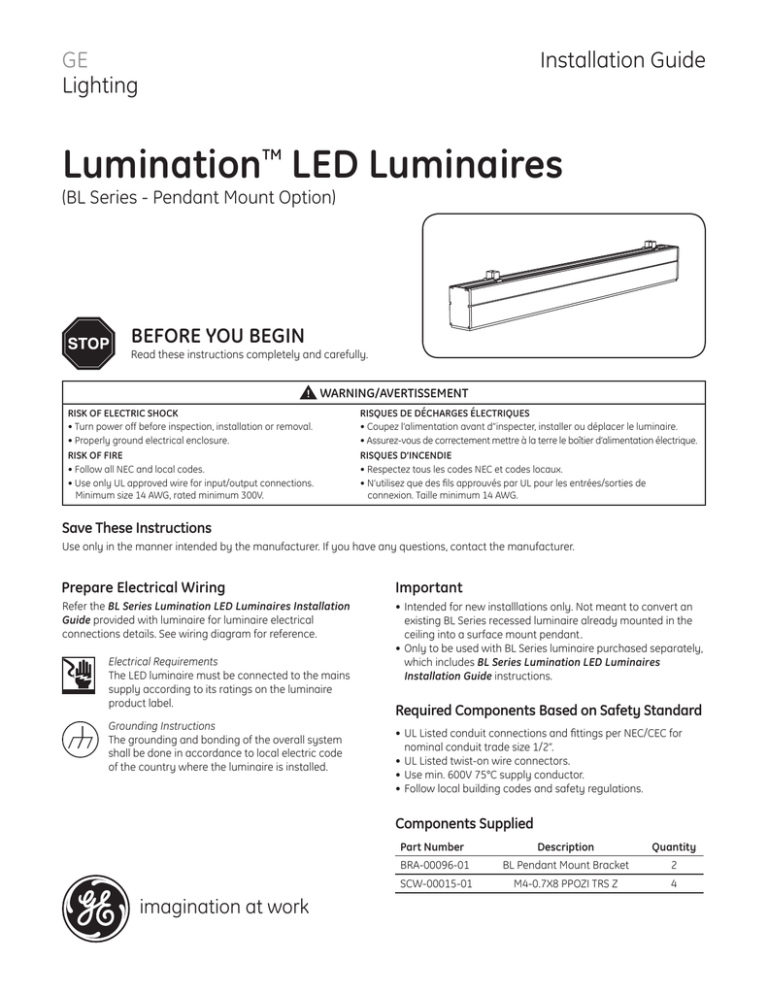
GE Lumination LED Fixtures BL Series Pendant Mount Option
advertisement

Installation Guide GE Lighting Lumination LED Luminaires TM (BL Series - Pendant Mount Option) BEFORE YOU BEGIN Read these instructions completely and carefully. WARNING/AVERTISSEMENT RISK OF ELECTRIC SHOCK • Turn power off before inspection, installation or removal. • Properly ground electrical enclosure. RISQUES DE DÉCHARGES ÉLECTRIQUES • Coupez l’alimentation avant d’’inspecter, installer ou déplacer le luminaire. • Assurez-vous de correctement mettre à la terre le boîtier d’alimentation électrique. RISK OF FIRE • Follow all NEC and local codes. • Use only UL approved wire for input/output connections. Minimum size 14 AWG, rated minimum 300V. RISQUES D’INCENDIE • Respectez tous les codes NEC et codes locaux. • N’utilisez que des fils approuvés par UL pour les entrées/sorties de connexion. Taille minimum 14 AWG. Save These Instructions Use only in the manner intended by the manufacturer. If you have any questions, contact the manufacturer. Prepare Electrical Wiring Important Refer the BL Series Lumination LED Luminaires Installation Guide provided with luminaire for luminaire electrical connections details. See wiring diagram for reference. •Intended for new installlations only. Not meant to convert an existing BL Series recessed luminaire already mounted in the ceiling into a surface mount pendant. •Only to be used with BL Series luminaire purchased separately, which includes BL Series Lumination LED Luminaires Installation Guide instructions. Electrical Requirements The LED luminaire must be connected to the mains supply according to its ratings on the luminaire product label. Grounding Instructions The grounding and bonding of the overall system shall be done in accordance to local electric code of the country where the luminaire is installed. Required Components Based on Safety Standard •UL Listed conduit connections and fittings per NEC/CEC for nominal conduit trade size 1/2”. •UL Listed twist-on wire connectors. •Use min. 600V 75°C supply conductor. •Follow local building codes and safety regulations. Components Supplied imagination at work Part Number Description Quantity BRA-00096-01 BL Pendant Mount Bracket 2 SCW-00015-01 M4-0.7X8 PPOZI TRS Z 4 Ceiling Mounting Method Options CAUTION Use mounting options that are appropriate for use with your mounting surface and weight of the fixture. OPTION 1 Mount to Building Structure Description: Mount fixture directly to building structural member such as: • Bar joists, strut, purlins, beams roof trusses, etc. Equipment Required (not supplied): • 1/4”-20 or M6 threaded rod • Contact supplier for other options OPTION 2 Mount to Ceiling Canopy Description: Mount fixture to ceiling canopies (not supplied). Equipment Required (not supplied): • Suspension cable • Single-feed Canopy Kit (67654) • Contact supplier for other options Wiring Diagram AC LED Driver Line Neutral Ground 1-10V(-) 1-10V(+) DALI/PROG. DALI/PROG. Black White Green/Yellow Grey Violet Violet/White Blue/White Black/White Yellow Remote Switch (Optional) NOTE: • Use appropriate connectors to make connections in accordance to local electric code of the country where the luminaire is installed as described in BL Series Lumination LED Luminaires Installation Guide instructions provided with the luminaire. • UL Listed conduit connections and fittings per NEC/CEC. • When connecting to (optional) switch, run wires from controller or dimmer through a different knockout than the AC input wire. Follow lighting controller installation instructions. Brackets Installation 1 Carefully unpack unit from its packaging. Properly inspect for defects before installing. Wear work gloves to prevent dirt and oil from being transferred to the luminaire. 2 Slide brackets into the top grooves of the fixture as shown. Use one bracket on each end of the fixture. 3 Move brackets to desired locations. Ensure brackets are not blocking wire access holes. 4 Use provided M4 tapping screws only. Turn each screw into bracket at an even amount so the bracket is push up by the screws evenly, until it is secured. 5 Repeat Step 4 for the other bracket. 6 Follow local building codes and acceptable mounting options. When using shoulder-bolt or threaded rod, 1/4”-20 or M6 is recommended for mounting into the ceiling structure. Use nut above and below bracket to prevent fixture movement. GE Lighting • 1-888-MY-GE-LED (1-888-69-43-533) • www.gelighting.com GE Lighting Solutions, LLC is a subsidiary of the General Electric Company. The GE brand, logo, and Lumination are trademarks of the General Electric Company. © 2014 GE Lighting Solutions, LLC. Information provided is subject to change without notice. All values are design or typical values when measured under laboratory conditions. IND124-072514


