24481707 740 Series Break Glass Release and Indicator
advertisement

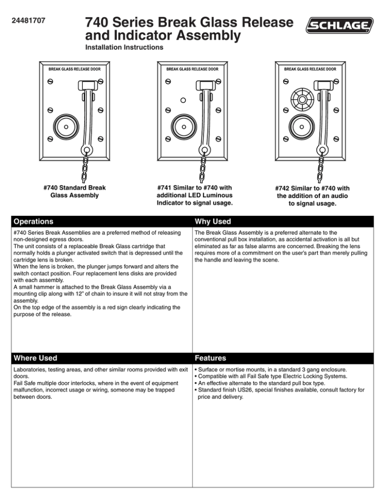
24481707 740 Series Break Glass Release and Indicator Assembly Installation Instructions #740 Standard Break Glass Assembly #741 Similar to #740 with additional LED Luminous Indicator to signal usage. #742 Similar to #740 with the addition of an audio to signal usage. Operations Why Used #740 Series Break Assemblies are a preferred method of releasing non-designed egress doors. The unit consists of a replaceable Break Glass cartridge that normally holds a plunger activated switch that is depressed until the cartridge lens is broken. When the lens is broken, the plunger jumps forward and alters the switch contact position. Four replacement lens disks are provided with each assembly. A small hammer is attached to the Break Glass Assembly via a mounting clip along with 12” of chain to insure it will not stray from the assembly. On the top edge of the assembly is a red sign clearly indicating the purpose of the release. The Break Glass Assembly is a preferred alternate to the conventional pull box installation, as accidental activation is all but eliminated as far as false alarms are concerned. Breaking the lens requires more of a commitment on the user’s part than merely pulling the handle and leaving the scene. Where Used Features Laboratories, testing areas, and other similar rooms provided with exit doors. Fail Safe multiple door interlocks, where in the event of equipment malfunction, incorrect usage or wiring, someone may be trapped between doors. • Surface or mortise mounts, in a standard 3 gang enclosure. • Compatible with all Fail Safe type Electric Locking Systems. • An effective alternate to the standard pull box type. • Standard finish US26, special finishes available, consult factory for price and delivery. Figure B Figure A Input Voltage Input Voltage On/Off Control On/Off Control Lock #740 Typical Wiring Standard Break Glass #741 Typical Wiring Standard Break Glass with Luminous Indicator Figure C Figure D Lock Input Voltage On/Off Control On/Off Control Lock #742 Typical Wiring Standard Break Glass with Audible Lock Typical Wiring shown when Lock Voltage and Break Glass are different Note: Figures B and C are shown with Break Glass being operated with voltage the same as the lock. For installations utilizing different operating voltages, see Figure D. Specifications Switch contacts rated 6 amps @ 120 VAC Screw type wiring connections Customer Service 1-877-671-7011 www.allegion.com/us © Allegion 2014 Printed in U.S.A. 24481707 Rev. 12/14-c 8.500 4.250 FRONT FRONT 2.750 FOLDED SHEET 11.000 BEGINNING SHEET Additional Notes: None A B N/A 33550 Revision History C D E F Revision Description: C > Allegion Rebranding 060572 Material White Paper Notes 1. printed two sides 2. printed black 3. tolerance: ± .13 4. see sheet 2 for artwork 5. printed in country may vary 6. drawings above not to scale Edited By Approved By EC Number Release Date R. Byun P. Bockelman 060572 12/05/2014 Title Installation Instruction, 740 Series Break Glass Release Creation Date Number 02/12/2013 Created By D. Myers Software: Illustrator CS6 24481707 Activity 3899 Hancock Expwy Security, CO 80911 Revision C Allegion Copyright © 2014


