statistical estimation of antenna gain from measurements carried out
advertisement
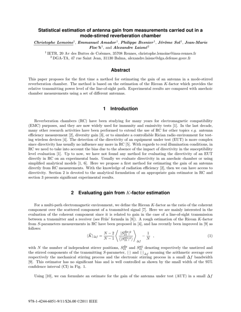
Statistical estimation of antenna gain from measurements carried out in a mode-stirred reverberation chamber Christophe Lemoine1 , Emmanuel Amador 1 , Philippe Besnier 1 , Jérôme Sol 1 , Jean-Marie Floc’h 1 , and Alexandre Laisné 2 1 IETR, 20 Av des Buttes de Coësmes, 35708 Rennes, christophe.lemoine@insa-rennes.fr 2 DGA-TA, 47 rue Saint Jean, 31130 Balma, alexandre.laisne@dga.defense.gouv.fr Abstract This paper proposes for the first time a method for estimating the gain of an antenna in a mode-stirred reverberation chamber. The method is based on the estimation of the Ricean K-factor which provides the relative transmitting power level of the line-of-sight path. Experimental results are compared with anechoic chamber measurements using a set of different antennas. 1 Introduction Reverberation chambers (RC) have been studying for many years for electromagnetic compatibility (EMC) purposes, and they are now widely used for immunity and emissivity tests [1]. In the last decade, many other research activities have been performed to extend the use of RC for other topics e.g. antenna efficiency measurement [2], diversity gain [3], or to simulate a controllable Rician radio environment for testing wireless devices [4]. The detection of the directivity of an equipment under test (EUT) is more complex since directivity has usually no influence any more in RC [5]. With regards to real illumination conditions, in RC we need to take into account the bias due to the absence of the impact of directivity in the susceptibility level evaluation [1]. Up to now, we have not found any method for evaluating the directivity of an EUT directly in RC on an experimental basis. Usually we evaluate directivity in an anechoic chamber or using simplified analytical models [1, 6]. Here we propose a first method for estimating the gain of an antenna directly from RC measurements. With the knowledge of radiation efficiency [2], then we can have access to directivity. Section 2 is devoted to the analytical formulation of an appropriate gain estimator in RC and section 3 presents significant experimental results. 2 Evaluating gain from K-factor estimation For a multi-path electromagnetic environment, we define the Ricean K-factor as the ratio of the coherent component over the scattered component of a transmitted signal [7]. Here we are mainly interested in the evaluation of the coherent component since it is related to gain in the case of a line-of-sight transmission between a transmitter and a receiver (see Friis’ formula in [8]). A rough estimation of the Ricean K-factor from S-parameters measurements in RC have been proposed in [4], and has recently been improved in [9] as follows: ⟨ ⟩ dir |2 N −2 |S21 1 b ⟨ sti ⟩ ⟨K⟩∆f = − , (1) 2 N −1 N |S21 | ∆f dir and S sti denoting respectively the unstirred and with N the number of independent stirrer positions, S21 21 the stirred components of the transmitting S-parameter, ⟨·⟩ and ⟨·⟩∆f meaning the arithmetic average over respectively the mechanical stirring process and the electronic stirring process in a small ∆f bandwidth [9]. This estimator has no significant bias and is well controlled as shown by the small width of the 95% confidence interval (CI) in Fig. 1. Using [10], we can formulate an estimate for the gain of the antenna under test (AUT) in a small ∆f 978-1-4244-6051-9/11/$26.00 ©2011 IEEE bandwidth, as a function of a reference antenna, as follows: ⟨ ⟩ b AUT K d2 b AUT = Gref × ⟨ ⟩ ∆f × AUT G , d2ref b ref K (2) ∆f with “ref” and “AUT” referring respectively to the reference antenna and the AUT, d the distance between the transmitter (position 1) and the receiving antenna (position 2) in line-of-sight configuration (see Fig. 2). Next we perform measurements respecting dAUT = dref in order to simplify the analysis. 30 Estimation of K (dB) 20 10 0 −10 K D E b Expected value of K −20 Lower bound of the 95% CI −30 −40 −40 ∆f Upper bound of the 95% CI −30 −20 −10 0 10 20 30 True value of K (dB) b ∆f using 50 inFigure 1: Expected value and 95% confidence interval associated with the estimation ⟨K⟩ dependent stirrer positions and 100 independent frequencies in the small ∆f bandwidth. This figure is the result of a Monte-Carlo simulation using 100 000 trials. 3 Experimental results The experimental setup consists in two similar steps which differ only with the use of either the reference antenna or the AUT as the antenna located in position 1 in Fig. 2. The 1st step uses the reference antenna ⟨ ⟩ b ref and leads to the estimation of K , whereas for the 2nd step we replace the reference antenna by the ∆f ⟨ ⟩ b AUT AUT leading to the estimation of K , and therefore to the estimation of its gain (eq. 2). For both ∆f steps the power injected into the chamber remains constant. In order to validate the proposed method, we use several Yagi printed antennas as AUT which differ only with the number of directors (Fig. 3), thus changing the gain. We performed measurements in the frequency range [2.5 GHz - 3.5 GHz], using a vector network analyzer with 5000 independent frequency points. We consider ∆f = 10 MHz leading to an electronic stirring process with 50 independent frequency points. Moreover, we use 100 independent stirrer positions for the mechanical stirring process. Therefore, each K-factor is estimated using 5000 independent data leading to a significant statistical estimation of the gain. The experimental results are presented in Fig. 4, for three different distances d, and five different antennas under test. Moreover, a comparison with anechoic Figure 2: Experimental configuration in the IETR reverberation chamber (2.9m × 3.7m × 8.7m). Figure 3: Yagi printed antennas with variable gain. chamber measurements and simulation results are provided. It is reasonable to say that using this method a reverberation chamber can provide a satisfying estimation of the gain of an AUT, especially for EMC testing for which we can accept more or less 3 dB of estimation uncertainty. 14 12 Gain (dB) 10 RC (d=0.5m) 8 RC (d=1m) 6 RC (d=5m) 4 Numerical simulation Anechoic chamber 2 0 1 5 8 12 Number of directors for the Yagi printed antenna Figure 4: Experimental results of the estimation of antennas gain in RC, in comparison with anechoic chamber measurements and simulation results. 4 Conclusion This paper proposes for the first time a method for estimating antenna gain in a mode-stirred reverberation chamber. The original method is based on the accurate estimation of the Ricean K-factor which provides the relative transmitting power level of the line-of-sight path. Although we used to consider that RC washes out the directivity [5], experimental results with a comparison with anechoic chamber measurements show that it is actually possible to have access to the gain of an antenna in RC. Using a third antenna in steps 1 and 2 of the proposed method, we can also estimate the AUT radiation efficiency [2], giving access to the directivity of the AUT. We will next focus our research activity on the directivity estimation of more complex systems than a single intentional emitter. The same method could be extended to large complex systems, locating the AUT inside the equipment under test with a control of the power injected into the chamber. 5 Aknowledgement This work was supported in part by the french Ministry of Defense DGA (Direction Générale de l’Armement), “REI” under Grant 2008 34004. References [1] IEC 61000-4-21: “Reverberation chamber test methods”, International Electrotechnical Commission Std., 2003. [2] K. Rosengren and P.-S. Kildal, “Radiation efficiency, corelation, diversity gain and capacity of a sixmonopole antenna array for a MIMO system: theory, simulation and measurement in reverberation chamber,” IEE Proc. Microwave Antennas Propagation, vol. 152, pp. 7–16, Feb. 2005. [3] P.-S. Kildal, K. Rosengren, J. Byun, and J. Lee, “Definition of effective diversity gain and how to measure it in a reverberation chamber,” Microwave Opt. Technol. Lett., vol. 34, pp. 56–59, July 2002. [4] C. L. Holloway, D. A. Hill, J. M. Ladbury, P. F. Wilson, G. Koepke, and J. Coder, “On the use of reverberation chambers to simulate a rician radio environment for the testing of wireless devices,” IEEE Trans. Antennas Propagat., vol. 54, no. 11, pp. 3167–3177, Nov. 2006. [5] M. Höijer, “Maximum power available to stress onto the critical component in the equipment under test when performing a radiated susceptibility test in the reverberation chamber,” IEEE Trans. Electromagn. Compat., vol. 48, no. 2, pp. 372–384, May 2006. [6] P. F. Wilson, D. A. Hill, and C. L. Holloway, “On determining the maximum emissions from electrically large sources,” IEEE Trans. Electromagn. Compat., vol. 44, no. 1, pp. 79–86, Feb. 2002. [7] J. D. Parsons, The mobile radio propagation channel. Chichester, England: John Wiley and Sons, 2nd edition, 2000. [8] C. Balanis, Antenna theory - analysis and design (2nd edition). New York, USA: John Wiley and Sons Inc., 1997. [9] C. Lemoine, E. Amador, and P. Besnier, “On the K -factor estimation for Rician channel simulated in reverberation chamber,” IEEE Trans. Antennas Propagat., vol. 59, no. 3, Mar. 2011. [10] V. Fiumara, A. Fusco, V. Matta, and I. M. Pinto, “Free-space antenna field/pattern retrieval in reverberation environments,” IEEE Antennas Wireless Propagat. Lett., vol. 4, pp. 329–332, 2005.
