Instruction Sheet
408-8594
Convenience Outlet 1445199-[ ]
09 DEC 11 Rev A
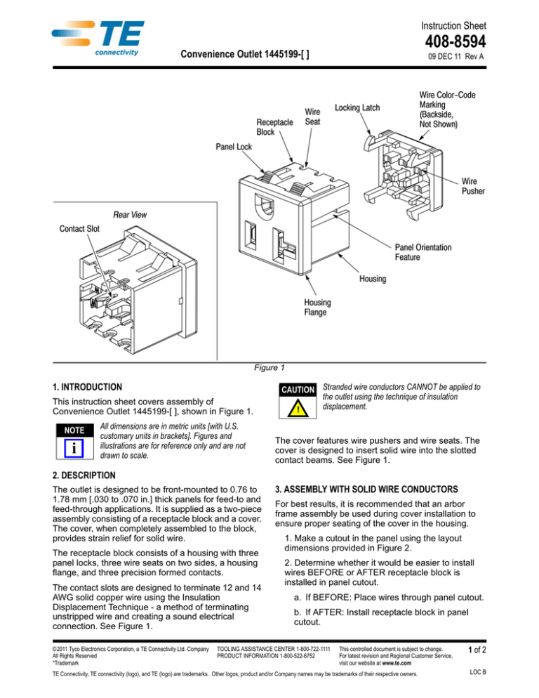
Figure 1
1. INTRODUCTION
This instruction sheet covers assembly of
Convenience Outlet 1445199-[ ], shown in Figure 1.
NOTE
i
All dimensions are in metric units [with U.S.
customary units in brackets]. Figures and
illustrations are for reference only and are not
drawn to scale.
CAUTION Stranded wire conductors CANNOT be applied to
the outlet using the technique of insulation
displacement.
!
The cover features wire pushers and wire seats. The
cover is designed to insert solid wire into the slotted
contact beams. See Figure 1.
2. DESCRIPTION
The outlet is designed to be front-mounted to 0.76 to
1.78 mm [.030 to .070 in.] thick panels for feed-to and
feed-through applications. It is supplied as a two-piece
assembly consisting of a receptacle block and a cover.
The cover, when completely assembled to the block,
provides strain relief for solid wire.
The receptacle block consists of a housing with three
panel locks, three wire seats on two sides, a housing
flange, and three precision formed contacts.
The contact slots are designed to terminate 12 and 14
AWG solid copper wire using the Insulation
Displacement Technique - a method of terminating
unstripped wire and creating a sound electrical
connection. See Figure 1.
©2011 Tyco Electronics Corporation, a TE Connectivity Ltd. Company
All Rights Reserved
*Trademark
3. ASSEMBLY WITH SOLID WIRE CONDUCTORS
For best results, it is recommended that an arbor
frame assembly be used during cover installation to
ensure proper seating of the cover in the housing.
1. Make a cutout in the panel using the layout
dimensions provided in Figure 2.
2. Determine whether it would be easier to install
wires BEFORE or AFTER receptacle block is
installed in panel cutout.
a. If BEFORE: Place wires through panel cutout.
b. If AFTER: Install receptacle block in panel
cutout.
TOOLING ASSISTANCE CENTER 1-800-722-1111
PRODUCT INFORMATION 1-800-522-6752
This controlled document is subject to change.
For latest revision and Regional Customer Service,
visit our website at www.te.com
TE Connectivity, TE connectivity (logo), and TE (logo) are trademarks. Other logos, product and/or Company names may be trademarks of their respective owners.
1 of 2
LOC B
408-8594
Figure 2
3. Place unstripped wires on appropriate contacts hot (black) on outer contact, ground (green) on
center contact, and neutral (white) on outer contact
labeled “W”. If making a feed-to-application, allow
each wire to extend approximately 6.35 mm
[.250 in.] beyond the contact beam.
CAUTION Do not attempt to push wires into contacts with a
flat-bladed screwdriver or any other tool that may
spread the contact beams and, as a result, cause a
!
loose connection.
4. Align cover with receptacle block; then press
cover straight into receptacle until it bottoms on
block. See Figure 3.
5. Install assembly in panel cutout if this was not
performed in Step 2b.
4. ORDERING INFORMATION
Order additional convenience outlets through your
TE Connectivity Representative, or call
1-800-526-5142, or send a facsimile of your purchase
order to 717-986-7605, or write to:
CUSTOMER SERVICE (038-035)
TYCO ELECTRONICS CORPORATION
PO BOX 3608
HARRISBURG PA 17105-3608
5. REVISION SUMMARY
• New logo
Rev A
Figure 3
2 of 2


