80459-651-01
06/2006
Seneca, SC, USA
Instruction Bulletin
Compac™ 6 Branch Feeder Unit
Customer Cable Loading Wiring
Class 8998
Retain for future use.
INTRODUCTION
This bulletin provides instructions for breaking the magnetic path in the
vertical wireway barrier between two cable entry areas. Follow these
instructions when installing load cables for 175, 200, 225, and 250 A
Compac™ 6 branch feeder units.
The Compac 6 branch feeder unit is equipped with a 6-in. (152 mm) high
opening into the vertical wireway that customers can use to install load
cables. When equipped with a vertical wireway barrier, these cables may
best fit in the unit when installed through two separate openings provided in
the barrier. If the cables are inserted through two of the separate openings,
a strip of steel separates the A-, B-, and C-phase cables.
SAFETY PRECAUTIONS
DANGER
HAZARD OF ELECTRIC SHOCK, EXPLOSION, OR ARC FLASH
• Apply appropriate personal protective equipment (PPE) and follow safe electrical work
practices. See NFPA 70E.
• This equipment must only be installed and serviced by qualified electrical personnel.
• Turn off all power supplying this equipment before working on or inside equipment.
• Always use a properly rated voltage sensing device to confirm power is off.
• Replace all devices, doors and covers before turning on power to this equipment.
Failure to follow these instructions will result in death or serious injury.
INSTALLATION
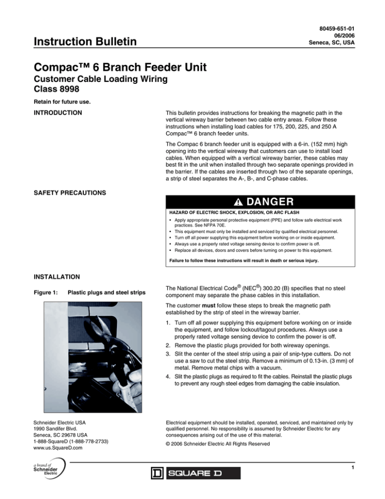
Figure 1:
Plastic plugs and steel strips
The National Electrical Code® (NEC®) 300.20 (B) specifies that no steel
component may separate the phase cables in this installation.
The customer must follow these steps to break the magnetic path
established by the strip of steel in the wireway barrier.
1. Turn off all power supplying this equipment before working on or inside
the equipment, and follow lockout/tagout procedures. Always use a
properly rated voltage sensing device to confirm the power is off.
2. Remove the plastic plugs provided for both wireway openings.
3. Slit the center of the steel strip using a pair of snip-type cutters. Do not
use a saw to cut the steel strip. Remove a minimum of 0.13-in. (3 mm) of
metal. Remove metal chips with a vacuum.
4. Slit the plastic plugs as required to fit the cables. Reinstall the plastic plugs
to prevent any rough steel edges from damaging the cable insulation.
Schneider Electric USA
1990 Sandifer Blvd.
Seneca, SC 29678 USA
1-888-SquareD (1-888-778-2733)
www.us.SquareD.com
Electrical equipment should be installed, operated, serviced, and maintained only by
qualified personnel. No responsibility is assumed by Schneider Electric for any
consequences arising out of the use of this material.
© 2006 Schneider Electric All Rights Reserved
1

