N
EW
Model 9410
Regenerative Grid Simulator
For The Testing of Grid-Tied Inverters, V2G, & Other AC Power Products
Key Features
8 models - 4kW/8kVA to 96kW/192kVA
Output AC Voltage - 0 to 310, 400VRMS L-N
Output Frequency - DC, 30 to 100Hz
Output DC Voltage - 200, 400VDC
Programmable 1, 2 or 3-Phase modes
Full 4-quadrant operation
High resolution waveform capture on all V & I
Sink power regenerated back to facility
9” Touch-Panel user interface
SCPI programming & NI LabVIEW drivers
Unique Power Modules Provide
Exceptional Configuration Flexibility
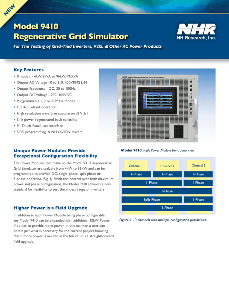
The Power Modules that make up the Model 9410 Regenerative
Grid Simulator are scalable from 4kW to 96kW and can be
programmed to provide DC, single-phase, split-phase or
3-phase operation (Fig. 1). With this control over both maximum
power and phase configuration, the Model 9410 achieves a new
standard for flexibility to test the widest range of inverters.
Model 9410 single Power Module front panel view
Channel 1
Channel 2
Channel 3
1-Phase
1-Phase
1-Phase
1-Phase
1-Phase
1-Phase
Split-Phase
Higher Power is a Field Upgrade
In addition to each Power Module being phase configurable,
any Model 9410 can be expanded with additional 12kW Power
Modules to provide more power. In this manner, a user can
obtain just what is necessary for the current project knowing
that if more power is needed in the future, it is a straightforward
field upgrade.
1-Phase
3-Phase
Figure 1 - 3 channels with multiple configuration possibilities.
More Reactive Power Capability Per kW
% of Max RMS Current
The Model 9410 Regenerative Grid Simulator is rated in
100%
both true power (kW) and apparent power (kVA) in order
to optimally size the test system for the test requirements.
80%
True Power Envelope
The system is able to maintain full true power across a wide
60%
operating voltage range as well as maintain this true power
Apparent Power Envelope
level even when additional reactive power (kVARS) or reactive
40%
current harmonics are present (Fig. 2). Sizing a traditional kVAonly rated system for true power must account for the worst20%
case power factor and the effects due to current harmonics.
0%
For example, a 45kVA-only rated system is able to provide
0%
20%
40%
60%
80%
100%
45kW when the power factor is unity (pf=1) but only able to
% of Max RMS Voltage
provide only 30kW when there is an equal amount of reactive
power (pf=0.7). In order to provide 45kW at a 0.7 power
Figure 2 - Model 9410 Operating Envelopes.
factor a 64kVA system is required. This sizing can be even
more complicated when reactive current harmonics are considered. The Model 9410 simplifies this selection process by allowing
the system to be specified in true power while still providing a higher VA rating to support reactive power needs. For example,
A 9410-48 system is rated to provide up to 48kW of power and is able to maintain an apparent power of up to 96kVA, thereby
meeting the needs for both true power and reactive power transfer requirements.
Hundreds of Precision Measurements
The Model 9410 includes a built-in measurement system which provides the power analysis tools typically found in digital multimeters, oscilloscopes, and power analyzers. Having such a comprehensive measurement system eliminates the integration complexity,
start-up time, extra cabinet space and cost for the additional measurement instruments normally required. The user is ready to begin
testing the day the Grid Simulator is delivered.
The types of measurements are practically limitless. In a 3-Phase Power Module, all six channels of V & I measurements are
digitized simultaneously at 1KS/s to be displayed, recorded or further analyzed. Specialized measurements such as abnormal grid
detection thresholds, disconnection timing, power ramp-up timing, and generated harmonic current limits are possible. The
number of such specialized measurements is limited only by the users’ capability to create additional measurement algorithms.
User Defined Waveshapes
In addition to several standard waveshapes, the Model 9410 has the ability to generate custom voltage waveshapes. These
waveshapes can be created by two different methods. First would be through downloading a table of numbers that correspond
to the desired value of each point over the entire cycle. A second method of creating custom waveshapes is through a NH
Research designed graphical waveshape editor. This provides actual manipulation of the waveshape and allows adding asymmetrical
inflections, transient anomalies, harmonics, and any other wave shape that can be drawn as a single-cycle.
The output voltage amplitude and frequency are independently programmable so that the basic wave shape can be used with other
voltages and frequencies. Additionally, each test channel/phase can use its own separate wave shape allowing the most versatility in
creating a simulated grid condition.
More Ranges for Improved Voltage & Current Accuracy
Model 9410 provide a selectable high/low range for both voltage and current. This separate range control significantly improves
set-point and measurement accuracy especially when compared to single-range or dual-range, voltage-only control. A 9410 test
channel can be set to operate and measure in the optimum range for both voltage and current. Through this capability, the tester
can be programmed in any combination of these ranges thereby providing four effective ranges including low-voltage/low-current,
low-voltage/high-current, high-voltage/low-current and high-voltage/high-current.
Soft Panel
1
Operation settings
2
Waveshape editor &
program representation
3
Actual measurements
4
Internal scope display
Figure 3 - This shows a grid
where one phase is likely
a UPS operating (squareish sine wave), one phase
is sinusoidal, and one is a
clipped sine (sagging voltage
at peak current).
1
2
3
4
Physical Connections & Controls
1
2
4
5
6
7
3
12
11
8
10
9
Touch Panel Based Control & Display
51) Output Power Control & Measurement
9
Remote Emergency Off
2
Status Lights & Trigger
61) Options Switch
10
Auxiliary Configuration
3
Circuit Breakers
71) LAN (Ethernet) Port
11
Input AC Power Terminal
4
External Sense
81) Parallel Connections
12
Chassis Ground
1
8
Model 9410 Regenerative Grid Simulator Specifications
Model Number
9410-4
9410-8
9410-12
9410-24
AC Output Ratings
Phases/Output Channels
Power, Max (1ф or 3ф)
Current Ranges (RMS per ф)
Current Ranges (RMS 1ф)
Peak Current
Frequency
Voltage Ranges, L-N
Accuracy
Resolution
Distortion (THD)
Response Rate
Custom Waveforms
Phase Angle Control
DC Output Ratings
Power Max ( 1ch or 3ch)
Current Ranges (Per Ch.)
Current Ranges (Per System)
Voltage Ranges
Accuracy
Ripple
AC & DC Measurements
Peak Voltage
Accuracy (AC RMS)
Accuracy (DC)
Accuracy (Peak)
Resolution
Peak Current (per Ch.)
Accuracy (AC RMS)
Accuracy (DC)
Accuracy (Peak)
Resolution
Peak Power
Accuracy (kW or kVA)
Resolution
Additional Measurements
Waveform Digitizer
Data Acquisition
Sample Rate
Memory Depth
Aperture Time
Accuracy/Resolution
Control
Local User Interface
External System Comm
Drivers
Safety
Module Protection
Physical
Programmable Limits
Software Watchdog
Physical
Connectors
Form
Dimensions (WxDxH)
Weight
Operating Temp
Isolation
Input Power
Voltage
Efficiency/Power Factor
Current per ф @ 380 V
Current per ф @ 400 V
Current per ф @ 480 V
Universal Input – 380V to 480V ± 10% (L-L, 3 Phase, 50/60Hz)
> 85% / > 0.95
9A
17A
25A
49A
9A
17A
24A
47A
8A
14A
20A
39A
Ordering Information
Grid Emulator P/N
Model
9410
1
1 or 2
1, 2, or 3
4kW/8kVA
8kW/16kVA
12kW/24kVA
24kW/48kVA
6, 30A/ф
6, 30A/ф
6, 30A/ф
12, 60A/ф
6, 30A
12, 60A
18, 90A
36, 180A
3 X Max RMS
30 – 100Hz
155, 310V, 400V Option
0.2% Set + 0.2% Rng
0.005% Rng
<1% @ 50/60Hz (Full power into resistive load at 480VRMS (L-L) )
1V/µS (10% to 90% measured at 90 degree turn-on into resistive load)
Sine, n-Step Sine, Triangle, Clipped-Sine, Arbitrary (user defined)
0 to 359 degrees / 1 degree resolution
4kW
8kW
6, 30A/CH
6, 30A/CH
6, 30A
12, 60A
200, 400VDC
0.2% Set + 0.2% Rng
< 800mV RMS
12kW
6, 30A/CH
18, 90A
24kW
12, 60A/CH
36, 180A
9410-36
9410-48
9410-72
9410-96
36kW/72kVA
18, 90A/ф
54, 270A
48kW/96kVA
24, 120A/ф
72, 360A
72kW/144kVA
36,180A/ф
108, 540A
96kW/192kVA
48, 240A/ф
144, 720A
36kW
18, 90A/CH
54, 270A
48kW
24, 120A/CH
72, 360A
72kW
36, 180A/CH
108, 540A
96kW
48, 240A/CH
144, 720A
80, 400A
120, 600A
180, 800A
250, 500V
0.1% Rdg + 0.06% Rng.
0.1% Rdg + 0.1% Rng.
0.5% Rdg + 0.2% Rng.
0.005% Rng
20, 100A
20, 100A
20, 100A
40, 200A
60, 300A
0.2% Rdg + 0.06% Rng.
0.2% Rdg + 0.06% Rng.
0.5% Rdg + 0.2% Rng.
0.005% Rng
V range x I Range
0.3% Rdg + 0.025% Rng.
0.005% Rng
Energy (Ah, kWh, kVAh), AC Crest Factor, AC Power Factor, Waveform Capture
Output Voltage and Current
125kSamples / sec
64kSamples
1 cycle to 64s
0.5% Rng / 0.05%
Built-in Touch-Panel and PC-Based software tools including graphical user interface
LAN (Ethernet) supporting SCPI or VX-11
NI-Certified LabVIEW Drivers, IVI-C, IVI-COM
Self-protecting for over-voltage, over-current, over-power, and over-temperature
Emergency Stop and remote E-Stop connection
Min/Max Voltage, Current (per direction), and Power (per direction) with separate limits and time delay values
Programmable
Terminal Block
Bus Bars
Chassis
Single Cabinet
19”x24”x15¾”
23”x30”x43”
23”x30”x78”
23”x30”x78”
105 lbs
120 lbs
135 lbs
370 lbs
505 lbs
855 lbs
35°C
Facility to Chassis – 1,000V, Output to Chassis – 500 V, Facility to Output Internal Isolation – 2,000 V
kW Rating
-12
73A
69A
58A
97A
92A
77A
Double Cabinet
46”x30”x78”
1340 lbs
1610 lbs
144A
137A
114A
192A
183A
152A
Options
-HV
16601 Hale Avenue, Irvine, California 92606
Tel: (949) 474-3900
E-mail: sales@nhresearch.com
www.nhresearch.com
© Copyright 2016, NH Research Incorporated. Pub 03-15-16 JC
All rights reserved. Specifications subject to change without notice.


