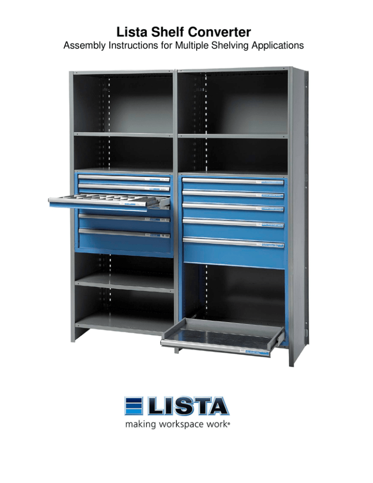
Lista Shelf Converter
Assembly Instructions for Multiple Shelving Applications
Table of Contents
Safety Check List.................................... 2
Existing Shelving Assembly Notes ....... 3
Three Basic Assembled Types.............. 3
Recommended Drawer Locations ......... 3
Tools Required ....................................... 4
Parts Included......................................... 4
Frame Identification................................ 5
Assembly Steps ......................................5
1. Frame Hardware.............................. 5
2. Shelf Location ................................. 6
3. Frame Assembly ............................. 7
4. Spacer Assembly.......................... 10
5. Drawer Installation........................ 11
6. Optional Hinge Lock Bar .............. 13
Read instructions entirely before assembling
Shelf Converter must be installed on fully assembled shelving
Always take precautions to ensure personal safety as well as shelf stability during the entire
installation process
Safety Check List
Shelf Converter is intended to only be installed on a safe, stable & anchored shelving
system. The following requirements must be followed:
• Drawers & loads must be with-in shelving manufacturer’s published capacity
• Shelving unit(s) must be anchored
• Stacked drawer units must have a shelf between them
• Stacked drawer units shall not exceed 62” in combined height
(Height Example: 36” unit + 18”unit = 54” combined unit height)
• Shelving unit(s) need to be level front to back & left to right
• Shelving unit(s) need to be plumb & square
Shelving unit(s) must be anchored
Use of Lista drawers & trays on un-anchored
shelving units can result in serious injury. See
shelving manufacture’s instructions
Never exceed maximum shelf system capacities
Always refer to shelving manufacture’s guide lines
If Shelf Converter total load exceeds shelving manufacturers capacity Lista
recommends using multiple units with shelves between them.
Note: Shelf spacing typically determines total shelf system capacity. Refer to shelf
manufacture’s guide lines regarding load capacities based on shelf spacing.
Lista Shelf Converter load capacities (Independent of shelving capacity):
18” = 2640 lbs
2
24” = 3520 lbs
36” = 5000 lbs
48” = 3200 lbs
Existing Shelving Assembly Notes
Installation of Shelf Converter into existing shelving may require the removal of some
shelving components or hardware. If so remove only one piece at a time, then re-install
once the Lista part is in place. Shelf Converter may not work with all shelving accessories.
Metalware Note: Shelves mounted adjacent to Lista Shelf Converter, may need to be
bolted into place. Optionally shelves may be moved above or below the drawer section to
allow use of shelf clips. Ask your Lista representative about optional shelf mounting
hardware (1/4-20 x 5/8” bolt & nut)
Metalware Shelving on:
Just one side
Both sides
Solution for adjacent shelf:
Slide shelf converter frame opposite shelf (after step-4)
Use hardware to bolt shelving in place (after step-2)
Three Basic Assembled Types
Stacked drawer sections must have a shelf between them.
Recommended Drawer Locations
Before assembling consider the most frequent body position when accessing the drawers:
• A sitting posture should have the top drawer between 35” & 42” from the floor.
• A standing posture should have the top drawer between 48” & 60” from the floor.
• Install shelf intended to cap the drawers approximately 1-2” above where you desire the top
most drawer to be.
48” to 60”
35” to 42”
3
Tools Required
Mounting Hardware
Shown
• Allen Keys 3/16” & 5/32”
• Vise Grips or Channel Locks
• Phillips Screw driver & Work gloves
Possibly tools required by shelving vendor
F
E
Parts Included
D
Mounting Hardware
Quantity per kit
18” & 48”
24”
Type
16
20
A - Threaded Sleeve
C
B - SAE washer
32
40
48
C - Lock washer
D - Non Threaded Sleeve
E - ¼-20 x 1.8” screw
F - ¼-20 x 1” screw
G - ¼-20 x 1.5” screw
16
20
24
16
16
16
F - ¼-20 x 1” screw
Frame Hardware
8 per kit
I - Left Frame
J – Right Frame
K – Rear Spacer
L – Lower Spacer
M – Upper Spacer
Frame Parts
1 per kit
1 per kit
2 per kit
1 per kit
1 per kit
B
36”
24
20
20
20
2 per kit
B
A
G
24
24
24
F
Lista Drawers/Trays, Suspension & Safety Clips – Qty varies
I
M
Frame Parts Shown
L
4
J
K
Frame Identification
To aid identification each frame is labeled at the upper front as shown
Label
Assembly Steps
1. Frame Hardware
A. Install four ¼-20 X 1” hardware on each frame using 3/16” Allen Key…Eight total.
B. Turn all hardware to nearly flush
Do not use
Frame
Rear
Frame
Front
Frame Hardware
Items F
Do not use
Frame
Front
Threaded end
nearly flush
Right Frame
Shown Complete
5
C. Systems utilizing optional Hinge Lock Bar require installation of ¼-20 x 1.5” screw as
shown using 5/32” Allen Key. Turn completely until tight.
Hardware
Items G
2. Shelf Location
A. First identify which shelf will cap the top of the drawers. If needed add or change an
existing shelf to the desired height per shelving instructions. This will be the upper
shelf capping the drawers.
Shelves both above & below the drawer section are required.
B. Next install a lower shelf that will sit below the drawers. Space from the upper shelf as
follows;
Shelf Converter Height
“D” Shelf Distance
1” shelf
2” shelf
spacing
spacing
18” (450)
21”
22
24” (600)
27”
28
36” (900)
39”
40
48” (1200)
51”
52
6
3. Frame Assembly
Hardware Note: Lista provides enough mounting hardware to cover all applications. You
will have extra hardware remaining on all installations.
Assemble mounting hardware depending on application shown below:
Single Bay Hardware
Use quantities listed in table “Short Hardware per post” below
*
Uses Hardware:
A, B, B, C & F
Side by Side Bay Hardware
Use quantities in tables below based on application type
Kit Height
Short Hardware
per shelf post
18”
24”
36”
48”
4
5
6
4
*
Uses Hardware:
A, B, B, C & F
Kit Height
Long Hardware
per shelf post
18”
24”
36”
48”
3
4
5
3
Uses Hardware:
A, B, B, C, D & E
*or
7
* Shown mounted
on post (top view)
Frame Assembly Continued
A. Install hardware at 6”- 7” below the upper shelf. If this location is not available move
down to the next available hole. Keep threaded sleeves facing drawer side
B. Install remaining mounting hardware evenly spaced top to bottom as access allows.
Keep lower hardware with-in 6” of the bottom. Tighten with 3/16” Allen Key & Channel
Locks.
C. Repeat steps A & B for the remaining three posts
Note that hardware location need not be the same for all four posts since each side
frame has multiple holes available
6” – 7” typical
Or
Ref. A & B on page 7 for shelf locations
6” typical
Threaded sleeves face drawer side
Shelf units with brace
holes shown
Metalware Posts
Shown
8
Frame Continued
D. Slide left & right frames all the way onto mounting hardware
Right Frame Shown
Metalware uses
round holes as shown
Most shelving will use
long slots shown
Hardware shown after
frame installation
9
4. Spacer Assembly
Rear Spacers (Galvanized Metal)
A. Orient upper spacer with notches facing down & pass through square hole on left side,
then repeat for right side.
B. Move spacer so notches align with bottom of square on both sides. Move spacer down
until fully seated (as shown).
C. Repeat for bottom spacer.
A
Pass Through
B
Right
Frame front
Front Spacers (Painted Metal)
Upper Spacer Installation
A. Orient upper spacer as shown
B. Align holes & install two #10 screws
B
A
B
10
Move Down
Lower Spacer Installation
A. Locate lower spacer as shown
B. Align holes & install two #10 screws as shown
B
C
A
Side & Squareness Adjustment
It is important to turn all frame screws so the frame is square & fixed in place.
Failure to do so can result in drawers that do not function or function poorly.
C. Turn all four frame screws on both the left & right frames so they are all equal.
This will square & center the frame in the shelf bay opening.
Re-install any shelving parts that were removed during assembly process &
Proceed to Drawer Installation
5. Drawer Installation
Lista Drawers & Trays consist of the following components:
Drawer or Tray
Safety Clips (two per
drawer/tray)
Track Pair
(one left, one right)
Suspension (one left, one right)
Front
Front
Use work gloves when handling U-tracks to avoid sharp edges
11
Drawer Installation
Start with one pair of Tracks, one stamped “L”, one stamped “R”
1. Orient “L” track to the left & “R” track to the right
Start at the bottom as shown
Track
Stamp
2. Insert left track rear tabs into rear retrofit bracket as
shown
Keep track level before inserting front track tabs. If needed relocate the
rear track tabs up or down one position for adjustment
3. Insert left track front tabs into front retrofit bracket and push down to locate.
It may be necessary to tap the front of the track down
with a mallet or dead blow hammer
Step 2.
Step 5.
4. Repeat same for the right track
5. Insert Safety clips as shown into each track
at the front slot
6. Orient Suspension Units – each unit is stamped L (for left) or R (for right), Install as
shown into each track
It may be necessary to lift each unit at the front when installing
PULL/OPEN
Step 7.
Step 6.
7. Pull plastic tabs out at the front of each suspension unit – Open position
8. Insert drawer or tray so side tracks ride on top of suspension unit’s lower wheels
It may be necessary to lift the front of the drawer/tray when installing
Step 8.
12
After drawer is installed always push both
plastic tabs in – Closed position (Step 9)
Failure to do so may result in personal injury
9. Push both plastic tabs all the way in as shown
After drawer/tray is installed
PUSH/CLOSED
Step 9.
10. Push drawer/tray all the way closed
Repeat for each drawer/tray
6. Optional Hinge Lock Bar
Hinge lock bar is available in left or right mount type (Left Shown Below)
No Lift Shelf Screws
The lock bar prevents drawers from being opened once locked. However, some shelf
manufacturer’s shelves can be lifted allowing access to the top drawer.
• For manufacturers with a shelf side return bend two ¼-20 x 1.5” screws can be
used to prevent the upper shelf from being lifted. Install one screw per frame at
the front top (as shown below) if not already installed. Turn screws to stop. This
should put the screw end above the shelf side return flange.
The rear brackets have a tab
that is designed to sit above the
shelf side flange. If needed the
tab can be bent by hand for
better alignment.
13
Hinge Lock Bar Continued
•
•
•
•
Align holes from the lock bar mounting bracket with holes on the face of the
Shelf Converter frame
Install #10 hardware provided with lock bar using #2 Phillips bit
Hang lock bar onto lock bar mounting bracket with pins
Install ring clip onto upper pin
Lock Bar Mounting
Bracket
Ring Clip
Lock Bar
Frame Face
14
This page left blank
15
Making Workspace Work ® is a trade mark of Lista International Corporation
Creation Date:
Document Number:
9-30-2010
SR003A3 Rev. 01
This document is proprietary information of Lista International Corporation. Unauthorized reproduction of any portion
of this document is prohibited without written consent of Lista International Corporation. The material in this document
is for informational purposes only. It is subject to change without notice.
© 2010 Lista International Corporation
106 Lowland Street
Holliston, MA 01746-2094
E-mail: sales@listaintl.com
All rights reserved
For questions or technical support call 1-800-722-3020
16


