APPLICATION
NOTES
Combining GDTs and MOVs for Surge
Protection of AC Power Lines
• 1.2/50µs-8/20µs Combination Wave
VOLTAGE (V)
1000
0
0.5µs to 100kHz
0.5 µs
10µs
100kHz
TIME
Figure 1a. IEEE C62.41
Location Categories A through C,
dependent on the distance of the
equipment from the service
entrance. Line cord-connected
equipment will usually be covered
by Location Category A or, occasionally, Location Category B.There
3000
CURRENT (A)
AC power line disturbances are the
cause of many equipment failures.
The damage can be as elusive as
occasional data crashes or as
dramatic as the destruction of a
power supply, computer terminal, or
television set. Power line disturbances go by many names -transients, surges, spikes, glitches, etc.
-- but regardless of the name, an
understanding of their characteristics
and the operation of the various
protection devices available is necessary to design an effective
protection circuit.This Application
Note will illustrate how to design
high performance, cost-effective
surge protection for equipment
connected to AC power lines.The
role of gas discharge tube (GDT)
surge arresters specifically designed
for AC power line protection will
also be discussed.
50%
PEAK
(Figure 1B) — a unidirectional
impulse waveform having a peak
open-circuit voltage of up to 6kV
(Note 1) with a rise time of 1.2µs
and a duration of 50µs (Note 2)
AND a peak short-circuit current of
up to 3kA (Note 1) with a rise time
of 8µs and a duration of 20µs (Note
3).
Test waveforms for evaluation of a
surge protection system should
conform to these standard waveforms as closely as possible to
ensure valid results.The use of test
waveforms having slower rise times
or lower peak currents/voltages may
result in a false sense of security
concerning the level of protection
actually provided under field conditions.
1000
METAL OXIDE VARISTOR
1000A
The first step in providing an effective defense against power line
transients is to accurately characterize the transients. One good
reference is IEEE C62.41-1991 entitled “IEEE Recommended Practice
on Surge Voltages in Low-Voltage
AC Power Circuits” (formerly IEEE
Standard 587).This standard defines
the open circuit voltage and short
circuit current waveforms which can
be expected to occur on AC power
lines of 1000 Volts (RMS) or less.
The standard defines three levels of
increasing transient activity, labeled
0
8
20
TIME (µs)
Figure 1b. IEEE C62.41
are two standard waveforms which
define the types of transients
expected in these Location
Categories:
VOLTAGE (V)
750
100A
500
25A
250
0.1A
0
0
5
10
15
20
25
TIME (µs)
Figure 2a. MOV clamping voltage at various current levels
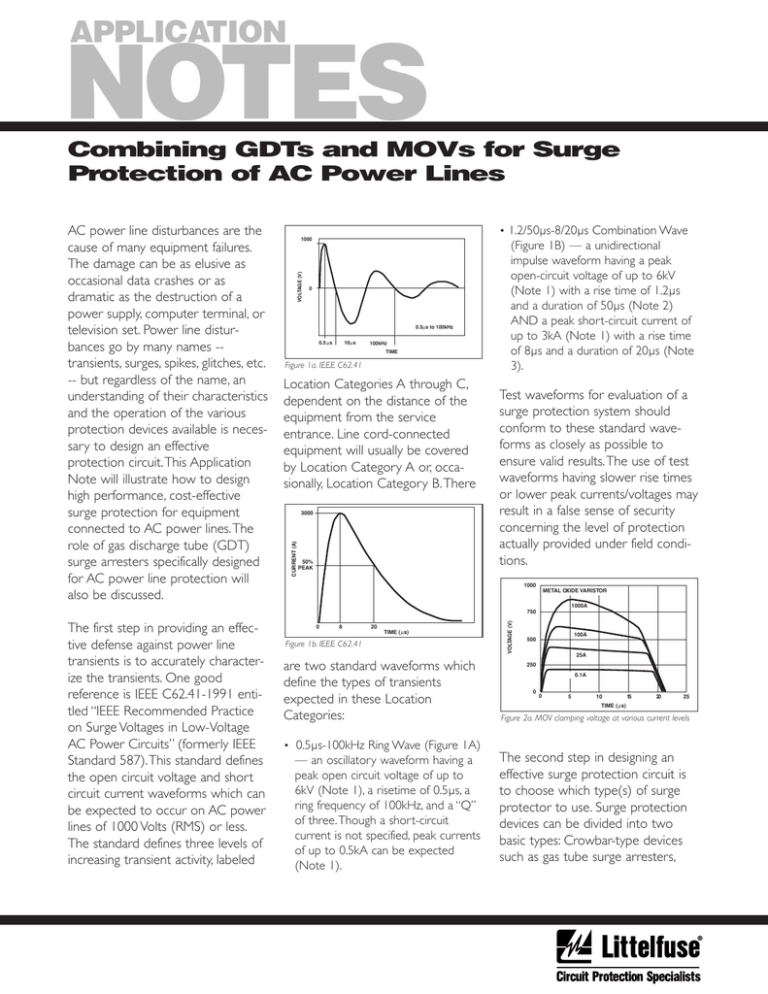
• 0.5µs-100kHz Ring Wave (Figure 1A)
— an oscillatory waveform having a
peak open circuit voltage of up to
6kV (Note 1), a risetime of 0.5µs, a
ring frequency of 100kHz, and a “Q”
of three.Though a short-circuit
current is not specified, peak currents
of up to 0.5kA can be expected
(Note 1).
The second step in designing an
effective surge protection circuit is
to choose which type(s) of surge
protector to use. Surge protection
devices can be divided into two
basic types: Crowbar-type devices
such as gas tube surge arresters,
The clamp-type devices have faster
response times but are limited in
their current handling ability because
most of the energy of the transient
must be dissipated by the clamping
device. Also, the voltage drop across
a clamp-type surge protector
1000
GAS TUBE SURGE ARRESTER
VOLTAGE (V)
750
500
250
0
0
5
10
15
20
25
TIME ( µs)
Figure 2b. Transient response of a plasma surge arrester
increases with the conducted
current as shown in Figure 2A.
Crowbar-type devices such as gas
tube surge arresters have slightly
slower response times but can
handle much higher current because
they act as a low impedance switch
which diverts the transient energy
away from the protected equipment
to be dissipated externally. While the
peak voltage experienced by the
protected circuit during the leading
edge of some transients may be
higher than with a clamp-type
device; the duration, and thus the
total energy delivered to the
protected circuit, is much lower
when using a crowbar-type device as
shown in Figure 2B.
This peak voltage is a function of the
rise time of the leading edge of the
transient. Faster rise times will result
in higher peak voltages due to the
response time of the protector.
Although Zener-gated SCRs and
thyristors are available which offer
faster response times, their use is
limited to telecom and signal line
applications due to their relatively
low peak current ratings. A major
benefit of the gas tube surge
arrester is that the voltage drop
across the device remains essentially
constant (<20V) regardless of the
conducted current.
The ideal surge protector would
overcome the current handling and
energy diverting characteristics of
the crowbar type device with the
speed of the clamp type device.This
approach has been difficult and
expensive to realize with traditional
crowbar type devices because their
designs were optimized for the ability to turn off in the presence of a
low-current DC bias. While that is
appropriate for protecting a telecom
line, additional components (such as
HOT
LOAD
NEUTRAL
GROUND
PLASMA SURGE
ARRESTERS
RFI FILTER
METAL OXIDE
VARISTORS
Figure 3a. Hybrid surge protection circuit
a series resistor or parallel
connected series-RC network) were
required to ensure that the gas tube
surge arrester would extinguish
when placed across an AC power
line with its relatively low source
impedance and the resultant followon currents (Note 4).These
components invariably decreased
the performance of the protector
while increasing its installed cost.
Gas tube surge arresters specifically
designed for AC power line applica-
tions provide the low impedance
switching action and high peak
current capabilities of traditional gas
tube surge arresters while optimizing the ability to extinguish in the
1000
750
VOLTAGE (V)
spark gaps, and SCRs; and Clamptype devices such as avalanche
diodes, transient absorption zener
diodes, and metal oxide varistors.
500
A
D
C
B
250
0
0
5
10
15
20
25
TIME (µs)
Figure 3b. Transient response of hybrid circuit
presence of AC follow-on currents
in excess of 300A. In most applications, no additional components are
required other than those of the
basic surge protection circuit. A
surge protection circuit with subnanosecond response time, precise
control of transient energy letthrough, and a peak current rating of
20,000A is now practical even for
cost-sensitive applications such as
power supplies, home stereos, monitors, and printers.
A typical installation is illustrated in
Figure 3A.This is a two stage hybrid
circuit consisting of a gas tube surge
arrester as the primary protector
and a Metal Oxide Varistor (MOV)
as the secondary protector.These
elements must be separated by an
isolating impedance.This impedance
may be either resistive (>10 Ω) or
inductive (>0.1mH) to ensure
proper coordination of the protective devices. Most AC applications
utilize an inductive element to minimize power dissipation and voltage
drop during normal operation.
The inductor used in this example is
part of the RFI filter already
required by the design.The output
of the protection circuit during a
transient is illustrated in Figure 3B.
The following sequence of events is
depicted in Figure 3B:
A.The leading edge of the transient
is clamped by the MOV to a value
just above the normal operating
voltage.
B. As the current through the MOV
increases, a voltage is developed
across the inductor which causes
the gas tube surge arrester to fire.
The energy of the transient is
now quickly shunted through the
gas tube surge arrester and away
from the protected circuit.
C.The gas tube surge arrester
remains in full conduction for the
duration of the transient.
D. When the transient has passed,
the gas tube surge arrester extinguishes—ready for the next
transient.
This circuit uses each component to
do what each does best: the gas
tube surge arrester diverts the highenergy portion of the transient and
the MOV provides the fast, accurate
clamping of the low energy leading
edge.
The cost effectiveness of this
protection circuit is enhanced by
three factors:
1.The use of an AC line gas tube
surge arrester eliminates the need
for additional components to
ensure turnoff.
2.The isolating impedance is
supplied by an existing component
(the RFI filter).
3. A small diameter MOV (LA or
UltraMOV™ varistors) is used
since the gas tube surge arrester
handles the high-energy portion
of the transient.
The example duplicates the circuit
between Neutral and Ground in
addition to the Hot-to-Neutral
circuit.This provides protection
against Common Mode (both lines
surged relative to ground) as well as
Normal Mode (Hot-to-Neutral)
transients.This is important because
both types of transients are frequent
occurrences in the real world.The
failure to provide Common Mode
protection is one of the leading
causes of failure in many otherwise
solid designs.
The critical points in the selection of
the gas tube surge arrester are the
minimum DC breakdown voltage
(which must be higher than the
highest normal voltage expected on
the protected line) and the followon current rating (which must be
higher than the expected fault
current of the incoming supply line).
In this example, the minimum DC
breakdown voltage is calculated by
multiplying the normal line voltage
(120VRMS ) by 1.414 to obtain the
peak voltage and then adding an
appropriate guard band to allow for
normal variations in the supply voltage.
The MOV should be selected using
the same formula. When used in a
properly designed hybrid circuit, a
7mm or 10mm device is normally
adequate to handle the small leading-edge currents until the gas tube
surge arrester goes into conduction.
The inductor should have a value of
at least 0.1mH. If the inductance is
too low, the MOV may clamp the
transient voltage at a level that does
not allow the gas tube surge
arrester to go into conduction.This
would result in energy beyond the
ratings of the MOV.Tests have been
conducted using several common
RFI filters having inductances or 12mH with excellent results.
Hybrid surge protection circuits
incorporating HAC Series gas tube
surge arresters can provide costeffective protection against
transients that exceed even the
tough guidelines of IEEE C62.411991 for Location Categories A and
B.
Notes
1.The exact value is a function of
the Location Category and
System Exposure level. See the
IEEE spec for more detailed
information.
2.The rise time for an opencircuit voltage waveform is
defined as 1.67 x (t90 - t30 )
where t30 and t90 are the 30%
and 90% amplitude points on the
leading edge of the waveform.
The duration is defined as the
time from the virtual origin, t0
(where a line through t30 and t90
intersects the zero voltage axis),
to the 50% amplitude point of
the trailing edge of the waveform, t50 .
3.The rise time for an shortcircuit current waveform is
defined as 1.25 x (t90 - t10 )
where t10 and t90 are the 10%
and 90% amplitude points on the
leading edge of the waveform.
The duration is defined as the
time from the virtual origin, t 0
(where a line through t10 and t 90
intersects the zero current axis),
to the 50% amplitude point of
the trailing edge of the waveform, t50 .
4. If the current supplied by the
AC power line exceeds the
maximum follow-on current of
the gas tube surge arrester (typically, ~20A), the device will
continue to conduct, even at a
zero crossing of the AC voltage
signal, causing the gas tube surge
arrester to overheat and fail.
Littelfuse, Inc.
800 E. Northwest Highway
Des Plaines, IL 60016
www.littelfuse.com
Specifications, descriptions and illustrative material in this literature are as accurate as known at time of publication, but are
subject to change without notice. Littelfuse is a registered trademark of Littelfuse Incorporated.
EC640
Copyright © 2002 Littelfuse, Inc., All Rights Reserved. Printed in U.S.A. JANUARY 2002


