DC Electronic Load Selection
advertisement

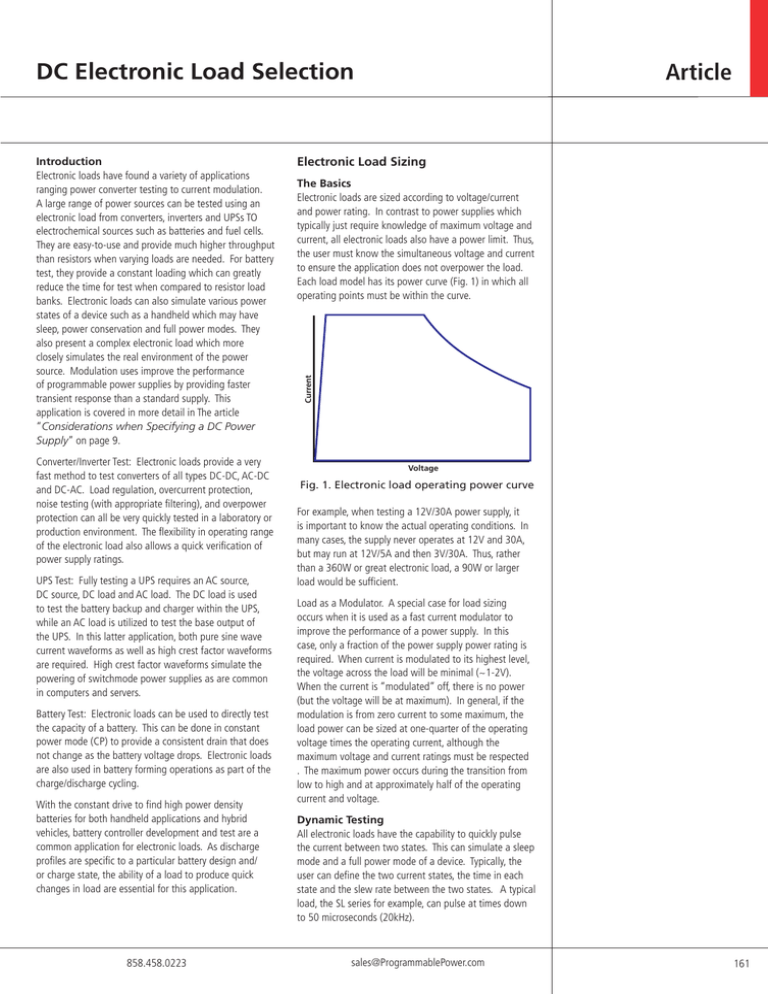
DC Electronic Load Selection Converter/Inverter Test: Electronic loads provide a very fast method to test converters of all types DC-DC, AC-DC and DC-AC. Load regulation, overcurrent protection, noise testing (with appropriate filtering), and overpower protection can all be very quickly tested in a laboratory or production environment. The flexibility in operating range of the electronic load also allows a quick verification of power supply ratings. UPS Test: Fully testing a UPS requires an AC source, DC source, DC load and AC load. The DC load is used to test the battery backup and charger within the UPS, while an AC load is utilized to test the base output of the UPS. In this latter application, both pure sine wave current waveforms as well as high crest factor waveforms are required. High crest factor waveforms simulate the powering of switchmode power supplies as are common in computers and servers. Battery Test: Electronic loads can be used to directly test the capacity of a battery. This can be done in constant power mode (CP) to provide a consistent drain that does not change as the battery voltage drops. Electronic loads are also used in battery forming operations as part of the charge/discharge cycling. With the constant drive to find high power density batteries for both handheld applications and hybrid vehicles, battery controller development and test are a common application for electronic loads. As discharge profiles are specific to a particular battery design and/ or charge state, the ability of a load to produce quick changes in load are essential for this application. 858.458.0223 Electronic Load Sizing The Basics Electronic loads are sized according to voltage/current and power rating. In contrast to power supplies which typically just require knowledge of maximum voltage and current, all electronic loads also have a power limit. Thus, the user must know the simultaneous voltage and current to ensure the application does not overpower the load. Each load model has its power curve (Fig. 1) in which all operating points must be within the curve. Current Introduction Electronic loads have found a variety of applications ranging power converter testing to current modulation. A large range of power sources can be tested using an electronic load from converters, inverters and UPSs TO electrochemical sources such as batteries and fuel cells. They are easy-to-use and provide much higher throughput than resistors when varying loads are needed. For battery test, they provide a constant loading which can greatly reduce the time for test when compared to resistor load banks. Electronic loads can also simulate various power states of a device such as a handheld which may have sleep, power conservation and full power modes. They also present a complex electronic load which more closely simulates the real environment of the power source. Modulation uses improve the performance of programmable power supplies by providing faster transient response than a standard supply. This application is covered in more detail in The article “Considerations when Specifying a DC Power Supply” on page 9. Article Voltage Fig. 1. Electronic load operating power curve For example, when testing a 12V/30A power supply, it is important to know the actual operating conditions. In many cases, the supply never operates at 12V and 30A, but may run at 12V/5A and then 3V/30A. Thus, rather than a 360W or great electronic load, a 90W or larger load would be sufficient. Load as a Modulator. A special case for load sizing occurs when it is used as a fast current modulator to improve the performance of a power supply. In this case, only a fraction of the power supply power rating is required. When current is modulated to its highest level, the voltage across the load will be minimal (~1-2V). When the current is “modulated” off, there is no power (but the voltage will be at maximum). In general, if the modulation is from zero current to some maximum, the load power can be sized at one-quarter of the operating voltage times the operating current, although the maximum voltage and current ratings must be respected . The maximum power occurs during the transition from low to high and at approximately half of the operating current and voltage. Dynamic Testing All electronic loads have the capability to quickly pulse the current between two states. This can simulate a sleep mode and a full power mode of a device. Typically, the user can define the two current states, the time in each state and the slew rate between the two states. A typical load, the SL series for example, can pulse at times down to 50 microseconds (20kHz). sales@ProgrammablePower.com 161 DC Electronic Load Selection Low Voltage Testing Low voltage testing is common in fuel cell characterization and voltage regulators for computers. All electronic loads require a minimum voltage to fully turn on. This is shown on the power curve where the voltage does not go to zero at maximum current. The minimum voltage for maximum current is typically <1V. The majority of loads on the market will operate below this voltage but not necessarily at the full rated current. The SL series has very good low voltage capability with full current down to 0.6-0.8V. If operating voltages lower than this are required (due to a low voltage from the source or due to the source voltage minus the voltage drop due to cabling resistance), there are two solutions: use a power supply in series with the load to boost the voltage seen by the load or use a load with a higher current rating. The first solution works well for fixed load setting and has been integrated by some load manufacturers. However, this is a relatively high cost solution that also has technical issues under transient conditions. The power supply must be sized for the full current rating, but only requires 1 to 3 volts, just enough to boost the voltage fully into the load’s power curve. Whether integrated or an independent unit, the power supply is typically much slower than the requirement for the load. In pulsing or other load varying tests, the power supply cannot keep up with the transients required. The second solution is to select a load with a higher current rating than required. For example, the SLH-60120-600 load will sink 120A @ 0.8V. In a particular application, the power source operates at 1V. With cabling losses of 0.3V, the actual voltage at the load input is 0.7V. At this voltage the load would sink 0.7 divided by 0.8 times 120A = 105A. However, if the SLH-60-2401200 load is selected, with the same 0.8V full turn-on, a load of 210A could be pulled. This method retains the full programmability and bandwidth of the load. Operating Modes In the most common uses (modulator applications excepted), the load is used as either a resistor replacement (CR Mode) or a constant current (CC Mode) load. CR mode is used as a straightforward replacement in existing test systems. CC Mode is the most common usage of electronic loads. It allows the load to simulate a complex electronic system which has different power V battery is fully charged t Charging cycle further charging can damage the battery Fig. 2. Battery charging profile. An electronic load can test points along the curve to quickly verify proper operation of a battery charger. 162 states and draws a constant current based on the mode (sleep, partial function, full function or different radio power states wireless devices). Constant voltage mode (CV Mode) is used to test current sources, fuel cells and battery chargers. For battery chargers, it provides a replacement for an actual battery that takes a few seconds to test what could take hours with a real battery. The voltage setpoints of the load are sequenced to simulate different states of charge of the battery and hence different voltages. Constant Power mode (CP) is a somewhat newer operating mode. It is most commonly used for battery and fuel cell testing to determine the “storage” capacity. Other Considerations Although the majority of loads used are DC, there are many applications which require either fast, random slew rates or an AC signal on top of the DC level. These are typical in development phases for rechargeable battery controllers, fuel cells and magnet control. These applications require both a high bandwidth electronic load and the ability to generate an arbitrary waveform. The SL Loads have a 20khz bandwidth full scale across all DC models and up to 40-50kHz for small signal AC on a DC setpoint. These frequencies can be driven through analog control by either an arbitrary waveform generator or a signal generator depending upon the waveform desired. In battery controllers, the electronic load is in parallel with a power supply to simulate battery charge/ discharge cycles as may be seen in real applications for the controller in a hardware in the loop (HIL) system. In fuel cell testing, a high frequency, low amplitude current can be drawn to perform electrochemical impedance spectroscopy (EIS) for characterization of cell impedances. Other features may also be important depending upon the user’s method of control and monitoring requirements. Current monitoring outputs can provide a valuable feature to simplify and reduce the cost of viewing waveforms. These outputs typically provide a 0-10V output reference which can be directly input to an oscilloscope thereby eliminating the need for a separate current shunt. Programmed sequencing provides a method to simulate multiple test conditions without computer intervention with more precise step times not possible with computer control. Computer control through RS-232 or GPIB is common for larger programs and common workstations with Ethernet on the horizon. Summary Electronic loads have a variety of applications across a broad range of the power industry. In proper selection of a load, it is first important to consider the application requirements. Load selection can then become straightforward by ensuring that all test conditions fall within the power curve. Other considerations include load bandwidth, operating modes, analog inputs and outputs, sequencing and computer control. With the proper selection, an electronic load will provide an easy replacement for resistor banks with much more flexibility and better real-world correlation to electronic devices www.ProgrammablePower.com


