Zelio® Control Measurement Relays
Specifications and characteristics
Multifunction 3-phase supply control relays RM35TF
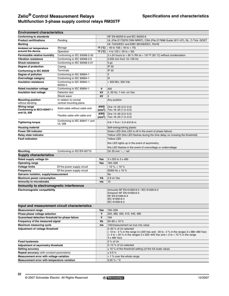
Environment characteristics
Conforming to standards
Product certifications
Marking
Ambient air temperature
around the device
Permissible relative humidity
Vibration resistance
Shock resistance
Degree of protection
Conforming to IEC 60529
Degree of pollution
Overvoltage category
Insulation resistance
Rated insulation voltage
Insulation test voltage
Mounting position
without derating
Wiring range
Conforming to IEC3 60947-1
and UL 508
Pending
Storage
Operation
Conforming to IEC 60068-2-30
Conforming to IEC 60068-2-6
Conforming to IEC 60068-2-27
Casing
Terminals
IP 20
Conforming to IEC 60664-1
Conforming to IEC 60664-1
Conforming to IEC 60664-1,
60255-5
Conforming to IEC 60664-1
Dielectric test
Shock wave
In relation to normal
vertical mounting plane
3
III
> 500 MΩ, 500 Vdc
Solid cable without cable end
Flexible cable with cable end
Tightening torque
NF EN 60255-6 and IEC 60255-6
UL (File E173076 CNN NRNT), CSA (File 217698 Guide 3211-07), GL, C-Tick, GOST
e: 73/23/EEC and EMC 89/336/EEC, RoHS
°F (°C) - 40 to 158 (- 40 to + 70)
°F (°C) - 4 to 122 (- 20 to + 50)
2 x 24 hours to + 95 % RH at + 131°F (55 °C) without condensation
0.035 mm from 10–150 Hz
5 gn
IP 30
V
kV
kV
AWG
(mm2)
AWG
(mm2)
Conforming to IEC 60947-1 and
UL 508
400
2, 50 Hz, 1 min. on Vac
4
Any position
One 14–20 (2.5–0.5)
Two 16–20 (1.5–0.5)
One 14–20 (2.5–0.5)
Two 16–20 (1.5–0.5)
0.6–1 N.m / 5.3–8.8 lb-in
Housing material
Power ON indicator
Relay state indicator
Fault indication
Self-extinguishing plastic
Green LED (this LED is off in the event of phase failure)
Yellow LED (this LED flashes during the time delay on crossing the threshold)
Yellow LED
this LED lights up in the event of asymmetry,
Mounting
this LED flashes in the event of overvoltage or undervoltage
On 35 mm 5 rail
Conforming to IEC/EN 60715
Supply characteristics
Rated supply voltage Un
Operating range
Voltage limits
Of the power supply circuit
Frequency
Of the power supply circuit
Galvanic isolation, supply/measurement
Maximum power consumption
Immunity to microbreaks
Vac
Vac
VA
ms
3 x 220 to 3 x 480
194–528
- 12 %, + 10 %
50/60 Hz ± 10 %
No
2.9 on Vac
10
Immunity to electromagnetic interference
Electromagnetic compatibility
Immunity NF EN 61000-6-2 / IEC 61000-6-2
Emission NF EN 61000-6-4
NF EN 61000-6-3
IEC 61000-6-4
IEC 61000-6-3
Input and measurement circuit characteristics
Measurement range
Phase-phase voltage selection
Guaranteed detection threshold for phase failure
Frequency of the measured signal
Maximum measuring cycle
Adjustment of voltage threshold
Fixed hysteresis
Adjustment of asymmetry threshold
Setting accuracy
Repeat accuracy (with constant parameters)
Measurement error with voltage variation
Measurement error with temperature variation
Vac
V
V
Hz
ms
194–528
220, 380, 400, 415, 440, 480
194
50–60 ± 10 %
140/measurement as true rms value
2–20 % of Un selected
(- 12 to - 2 % in the range 3 x 220 Vac and - 20 to - 2 % in the ranges 3 x 380–480 Vac)
(+ 2 to + 20 % in the ranges 3 x 220–440 Vac and + 2 to + 10 % in the range
3 x 480 Vac)
2 % of Un
5–15 % of Un selected
± 10 % of the threshold setting (of the full scale value)
± 0.5 %
< 1 % over the whole range
0.05 % / °C
22
© 2007 Schneider Electric All Rights Reserved
12/2007
Zelio® Control Measurement Relays
Specifications and characteristics, catalog
number, dimensions, wiring diagram
Multifunction 3-phase supply control relays RM35TF
F
Time delay characteristics
Time delay on crossing the threshold
Repeat accuracy (with constant parameters)
Reset time
Response time in the event of a fault
Delay on pick-up
s
ms
ms
ms
0.1–10. 0 + 10 %
± 0.3 %
1500 max at 480 V
< 200
500
Output characteristics
Type of output
Contact type
Maximum switching voltage
Rated breaking capacity
Current rating—Resistive (Inductive)
Minimum breaking current
Mechanical durability q
Electrical durability q
Maximum operating rate
Utilization categories
Conforming to IEC 60947-5-1
2 C/O contacts
Cadmium-free
Vac/Vdc 250
VA
1250
A
5 (1 A at 24 Vdc, 5 A at 24 Vac, 3 A at 250 Vac)
mA 10 /5 Vdc
30 x 106 operating cycles
1 x 10⁵ operating cycles
360 operations/hour under full load
AC-12, AC-13, AC-14, AC-15, DC-12, DC-13
q The expected life expressed above is based on average usage and normal operating conditions. Actual operating life will vary with conditions. The above statements
are not intended to nor shall they create any expressed or implied warranties as to product operation or life. For information on the listed warranty offered on this
product, refer to the Square D Conditions of Sale found in the Digest.
105670
Catalog number
Function
Rated 3-phase
supply voltage
Vac
Output
Catalog number Weight
•
•
•
•
220–480
2 C/O
5A
RM35TF30
Phase sequence
Phase failure
Asymmetry
Undervoltage and
overvoltage in
window mode
lb(kg)
0.286
(0.130)
RM35TF30
Approximante dimensions
Wiring diagram
RM35TF30
RM35TF30
35/1.38
14
11
21
22
24
12
90/3.54
11
R
22
21
24
2.8
0.11
12
L3
L2
L1
L2
L3
L1
14
72/2.83
76/2.99
72.5/2.85
mm/In.
23
12/2007
© 2007 Schneider Electric All Rights Reserved


