FC-VSM-1.0
12-12-07
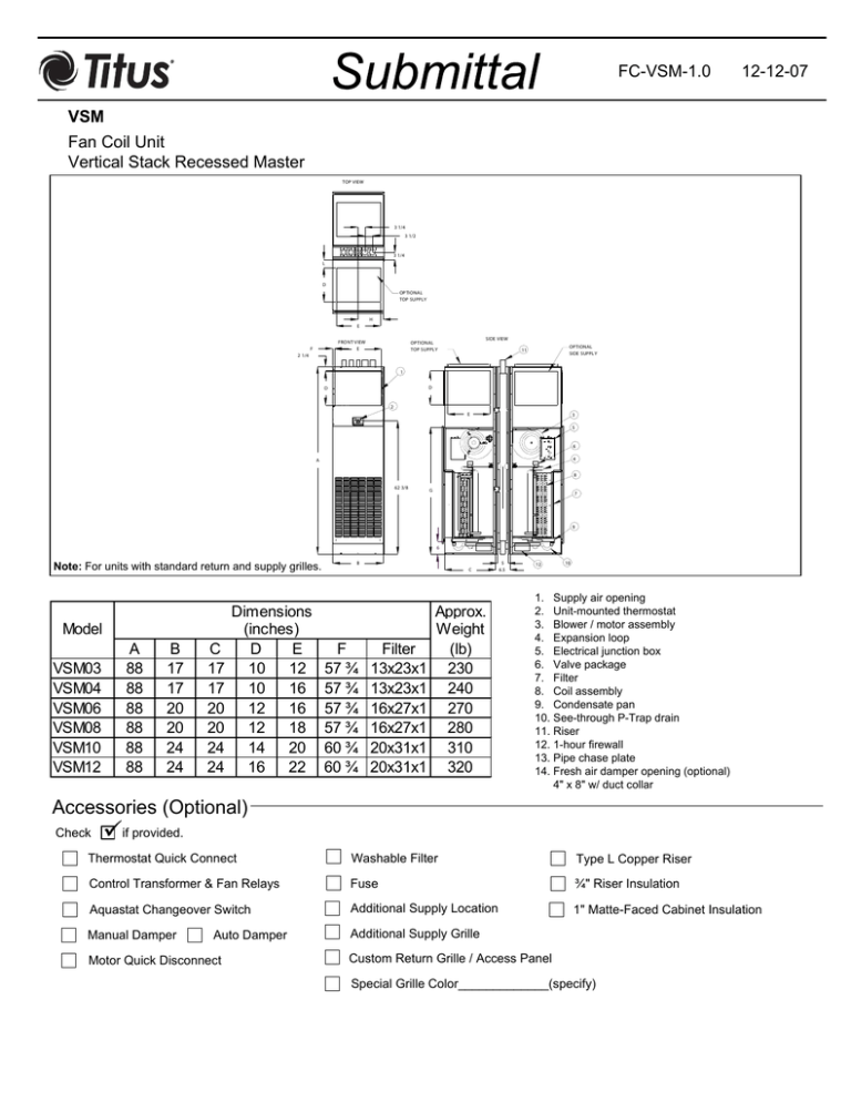
VSM
Fan Coil Unit
Vertical Stack Recessed Master
TOP VIEW
3 1/4
3 1/2
3 1/4
L
D
OPTIONAL
TOP SUPPLY
H
E
FRO NT V IEW
E
F
SIDE VIEW
OPTIONAL
TOP SUPPLY
OPTIONAL
SIDE SUPPLY
11
2 1/4
1
D
D
2
E
3
5
6
4
A
8
62 3/8
G
7
9
6
Note: For units with standard return and supply grilles.
Model
VSM03
VSM04
VSM06
VSM08
VSM10
VSM12
A
88
88
88
88
88
88
B
17
17
20
20
24
24
C
17
17
20
20
24
24
Dimensions
(inches)
D
E
10
12
10
16
12
16
12
18
14
20
16
22
B
C
F
57 ¾
57 ¾
57 ¾
57 ¾
60 ¾
60 ¾
Filter
13x23x1
13x23x1
16x27x1
16x27x1
20x31x1
20x31x1
Approx.
W eight
(lb)
230
240
270
280
310
320
5
6.5
12
10
1. Supply air opening
2. Unit-mounted thermostat
3. Blower / motor assembly
4. Expansion loop
5. Electrical junction box
6. Valve package
7. Filter
8. Coil assembly
9. Condensate pan
10. See-through P-Trap drain
11. Riser
12. 1-hour firewall
13. Pipe chase plate
14. Fresh air damper opening (optional)
4" x 8" w/ duct collar
Accessories (Optional)
Check
if provided.
Thermostat Quick Connect
Washable Filter
Type L Copper Riser
Control Transformer & Fan Relays
Fuse
¾" Riser Insulation
Aquastat Changeover Switch
Additional Supply Location
1" Matte-Faced Cabinet Insulation
Manual Damper
Additional Supply Grille
Auto Damper
Motor Quick Disconnect
Custom Return Grille / Access Panel
Special Grille Color_____________(specify)
Submittal FC-VSM-2.0
12-12-07
Accessories (Optional)
Coil - 3/8" O.D. Copper Tube; 10 Fins/Inch Aluminum, Sine Wave
2-Pipe
2-Row (STD.)
3-Row (STD.)
4-Row (STD.)
5-Row
3/2-Row
4/1-Row
4-Pipe (Cooling Rows/Heating Rows)
2/1-Row (STD.)
3/1-Row (STD.)
Chilled Water Cooling
Hot Water Heating
Glycol Cooling
Glycol Heating
Motor(s) - 3 speed PSC
Standard
115V/60Hz/1ph
Model
VSM03
HP
1
/8
208V/60Hz/1ph
Total
2.6
VSM04
1
2.6
VSM06
1
2.6
VSM08
1
2.6
VSM10
1
/8
2.6
VSM12
1
/3
5.8
/8
/8
/8
Electric Heat
(Single Phase)
Heater Voltage
115V
208V
230V
277V
Optional:
230V/60Hz/1ph
277V/60Hz/1ph
Features:
Automatic Reset
Thermal Overload
Protection System
Sleeve Bearings
Electric Heater kW Primary or Supplementary
115 Volts
208 Volts
230 Volts
277 Volts
Size Blowers Min-Max kW Min-Max kW Min-Max kW Min-Max kW
03
1
1-1.5 kW
1-2 kW
1-2 kW
1-2.5 KW
04
1
1-1.5 kW
1-2 kW
1-2 kW
1-2.5 KW
06
1
1-2.5 kW
1-3 kW
1-3 kW
1-3.5 KW
08
1
1-2.5 kW
1-3 kW
1-3 kW
1-3.5 KW
10
1
1-3 kW
1-3 kW
1-3.5 kW
1-5 kW
12
1
1-3 kW
1-3 kW
1-3.5 kW
1-5 kW
Submittal FC-VSM-3.0
12-12-07
Condensate Pan
Galvanized (STD.)
Description: Inner and
Outer Layer of 18 gauge
Galvanized Sheet Metal
with One - Inch Internal
Insulation.
Mastic Coating
Stainless Steel Inner Layer
Valves and Valve Accessories
Shut - Off Valve(s) (STD.)
Strainer(s)
Shut - Off Valve w/ Memory Stop
Fixed Flow Control(s)
2 - Way Motorized Valve (STD.)
Adjustable Flow Control(s)
3 - Way Motorized Valve
Unions
2 - Way Modulating Valve
Pete’s Plug(s)
General Description
•
This horizontal discharge, vertical
•
stack unit is designed for concealed
installations in high-rise hotels, motels,
apartment buildings and nursing
homes. The risers are incorporated
with the unit for quick and economical
installation.
Throwaway filter.
•
Line voltage thermostat
incorporating 3-speed switch
and manual change-over
switch.
•
Exterior fabricated of 18 gauge
galvanized steel with ½” matte-faced
liner for maximum thermal and
acoustical insulation, unpainted.
Manual Air Vent.
•
1-Hour fire wall in compliance
with ANSI/UL 1479. ETL
listed.
•
•
Removable motor/blower assembly
mounted on a deck which slides out for
easy maintenance.
Aluminum double deflection white
supply grille.
•
Unit disconnect switch on
internal junction box.
•
Riser assembly for 2 or 4-Pipe system •
including ½" closed cell, flexible
elastomeric thermal insulation. Risers
are swaged at one end for ease of
installation. Extensions are provided for •
connection to unit on the next floor.
Stamped Steel return air grille/access
panel, white with powder polyester
coated paint, oven baked.
•
System charged with air to
insure a leak free arrival at the
job site.
Transparent flexible P-Trap
drain.
•
One 2-Way motorized valve
with 2 shut-off valves for 2Pipe systems and two sets for
a 4-Pipe system.
This submittal is meant to demonstrate general dimensions of this product. The drawings are not meant to detail every aspect of the product. Drawings are not to scale. Titus
®
reserves the right to make changes without written notice.
605 Shiloh Road • Plano, Texas 75074• 972-212-4800
All rights reserved. No part of this work may be reproduced or transmitted in any form or by any means, electronic or mechanica
l, including photocopying and recording, or by any information storage retrieval system without permission in writing from Air Distribution Technologies


