LightSaver® LS-102 Switching Photosensor
advertisement
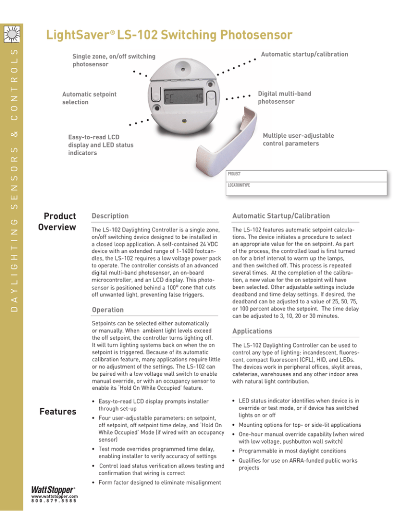
Dayl i ghti n g s e n s o rs & C o nt ro ls LightSaver® LS-102 Switching Photosensor Digital multi-band photosensor Automatic setpoint selection Multiple user-adjustable control parameters Easy-to-read LCD display and LED status indicators PROJECT LOCATION/TYPE Product Overview Description Automatic Startup/Calibration The LS-102 Daylighting Controller is a single zone, on/off switching device designed to be installed in a closed loop application. A self-contained 24 VDC device with an extended range of 1-1400 footcandles, the LS-102 requires a low voltage power pack to operate. The controller consists of an advanced digital multi-band photosensor, an on-board microcontroller, and an LCD display. This photosensor is positioned behind a 100º cone that cuts off unwanted light, preventing false triggers. The LS-102 features automatic setpoint calculations. The device initiates a procedure to select an appropriate value for the on setpoint. As part of the process, the controlled load is first turned on for a brief interval to warm up the lamps, and then switched off. This process is repeated several times. At the completion of the calibration, a new value for the on setpoint will have been selected. Other adjustable settings include deadband and time delay settings. If desired, the deadband can be adjusted to a value of 25, 50, 75, or 100 percent above the setpoint. The time delay can be adjusted to 3, 10, 20 or 30 minutes. Operation Setpoints can be selected either automatically or manually. When ambient light levels exceed the off setpoint, the controller turns lighting off. It will turn lighting systems back on when the on setpoint is triggered. Because of its automatic calibration feature, many applications require little or no adjustment of the settings. The LS-102 can be paired with a low voltage wall switch to enable manual override, or with an occupancy sensor to enable its ‘Hold On While Occupied’ feature. Features • Easy-to-read LCD display prompts installer through set-up • Four user-adjustable parameters: on setpoint, off setpoint, off setpoint time delay, and ‘Hold On While Occupied’ Mode (if wired with an occupancy sensor) • Test mode overrides programmed time delay, enabling installer to verify accuracy of settings • Control load status verification allows testing and confirmation that wiring is correct • Form factor designed to eliminate misalignment F15 Automatic startup/calibration Single zone, on/off switching photosensor www.wattstopper.com 800.879.8585 Applications The LS-102 Daylighting Controller can be used to control any type of lighting: incandescent, fluorescent, compact fluorescent (CFL), HID, and LEDs. The devices work in peripheral offices, skylit areas, cafeterias, warehouses and any other indoor area with natural light contribution. • LED status indicator identifies when device is in override or test mode, or if device has switched lights on or off • Mounting options for top- or side-lit applications • One-hour manual override capability (when wired with low voltage, pushbutton wall switch) • Programmable in most daylight conditions • Qualifies for use on ARRA-funded public works projects Wiring Diagram • Location: Suitable for dry interior locations • Environment: 32-120ºF (0-49ºC), less than 90% relative humidity • Dimensions: 2.4” diameter x 0.7” deep (61mm x 17mm) • Five year warranty • UL listed Mounting and LED Display Light Sensor Neut. White Hot / Line 120VAC BZ-150 Power Pack Red Red Menu Button Grey Orange Blue Brown Red FC 57 Cap both wires, not used Select Button +24VDC in Red Red Common Black Black Occupancy Input White Blue LVS-1 Switch or Equiv. (Optional) LS-102 Control Out Blue Mounting Screw Hole Display Status LED White/Yellow (cap if not used) Retaining Nut Plastic Washer For other wiring diagrams, please visit the CAD Resource Center at www.wattstopper.com se n sors Any 24VDC Occupancy Sensor Mounting Screw Hole Lighting Load 277VAC Black Wiring, Installation & Location • Automatic setpoint calculation • Digital Multi-Band Photosensor Range: 1-1400 footcandles • ON Setpoint Range: 1-850 footcandles • Status Indicator: Multi-function green LED • Power Requirements: 12/24 VDC; 7 mA typical • Output Signal: 24VDC; maximum 120 mA D ay lig h t ing Specifications Ceiling & Top Lighting Application LS-102 Skylight 1 Window 100˚ 2 Peak Sensitivity 100˚ 100˚ LS-102 Light Fixture Light Fixture Con trol s Side Lighting Application Typical Daylit Zone, about 12' (3.6m) Deadband Level Chart 100 Daylight 90 Electric Light 80 Footcandle 70 OFF Setpoint 60 ON Setpoint 50 Deadband 40 30 20 Energy Savings Opportunity 10 0 8am 9am 10am 11am 12pm 1pm 2pm 3pm 4pm 5pm 6pm 7pm 8pm If the LS-102’s photosensor lighting level drops below the on setpoint, the lights will remain on. If the sensor’s lighting level rises above the off setpoint, the LS-102 will automatically turn the lights off. If the sensor’s lighting level remains in the predetermined deadband range (25%, 50%, 75% or 100%) the lighting will be passive until the sensor’s level reaches the high or low setpoints. Time Ordering Information Catalog No. Description Footcandle Range Deadband Adjustment Range LS-102 On/Off Switching Photosensor 1-1400 fc 25%, 50%, 75% & 100% above on setpoint LS-102-U On/Off Switching Photosensor, ARRA-compliant 1-1400 fc 25%, 50%, 75% & 100% above on setpoint LS-102-FTA On/Off Switching Photosensor, ARRA-compliant (FTA exception) 1-1400 fc 25%, 50%, 75% & 100% above on setpoint Pub. No. 29504 rev. 11/2010 www.wattstopper.com | 8 0 0 . 8 7 9 . 8 5 8 5 F16
