DT0032
Design tip
VL6180X cross talk compensation implementation
By Colin Ramrattan
Main components
VL6180X
Proximity and ambient light sensing (ALS) module
Purpose and benefits
The purpose of this document is to explain how to implement the cross talk compensation
feature of the VL6180X.
It is assumed that customers who use this document can communicate with the VL6180X
2
through I C and are now looking for more information on how to implement the cross talk
compensation feature into their application code.
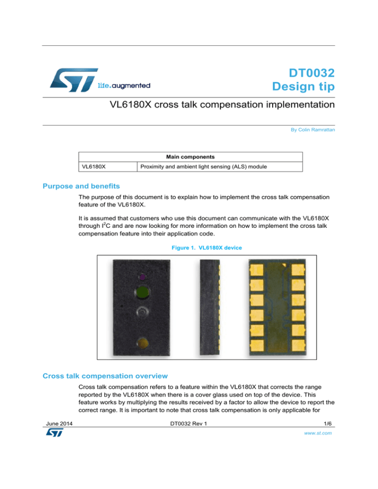
Figure 1. VL6180X device
Cross talk compensation overview
Cross talk compensation refers to a feature within the VL6180X that corrects the range
reported by the VL6180X when there is a cover glass used on top of the device. This
feature works by multiplying the results received by a factor to allow the device to report the
correct range. It is important to note that cross talk compensation is only applicable for
June 2014
DT0032 Rev 1
1/6
www.st.com
ranges greater than 20mm. Figure 2 shows picture of the cross talk noise that is referred
to.
Figure 2. Cross talk noise
Cross Talk
Noise
Cross talk compensation description
The cross talk compensation factor is a parameter set by the HOST system. In a normal
production environment, this setting is characterized and then loaded at each boot up of
the device. A simple diagram of how this compensation works is shown below in 3.
Figure 3. Cross talk compensation
Resulting Range
20mm
20mm
Raw Range
As shown above in the left hand image of 3, as the measured range increases, the actual
range, which is comprised of the raw range reported by the VL6180X system, does not
accurately report the distance of the target due to the extra noise introduced by cover
glass. To compensate for this, the cross talk compensation factor labeled “Stray
Compensation” on the left side of Figure 3 is applied to the raw range and the resulting
range is the accurate distance of the object. Also, the return signal rate shown as “Signal
Rate” on the right side of Figure 3, is at its peak as a target of below or around 20 mm. As
June 2014
DT0032 Rev 1
2/6
www.st.com
the target is moved further away, the return signal rate decreases, which will allow the
cross talk compensation to be applied correctly.
Calibrating the cross talk compensation
To apply the cross talk compensation factor in the VL6180X, the cross talk calibration must
be completed. In a normal end application, this would be done by performing cross talk
calibration on a production lot of the end user application devices. This will ensure that the
average of the cross talk calibration factor is captured with all of the expected mechanical
tolerances.
To perform cross talk calibration, a black 3% reflective target is placed at 100mm above the
VL6180X device in the end application. This is shown in Figure 4.
Figure 4. Cross talk calibration setup
Black 3% Reflective Target
100mm Distance
Cover Glass/Plastic
VL6180X
Application Hardware
Then the HOST system will capture at least 10 measurements to ensure the average is
representative of the cross talk in the system. The values then read from
RESULT__RANGE_RAW Reg 0x0064 and also the RESULT__RANGE_RETURN_RATE
Reg 0x0066 after each measurement is completed. These raw range measurements and
the return signal rate are averaged to get average raw range and average return signal rate
and are divided by 100mm to get a ratio or cross talk compensated factor. This value is
multiplied by 128 and then written to the
SYSRANGE__CROSSTALK_COMPENSATION_RATE, Reg 0x001E. Please note the
signal return rate from Reg 0x0066 is stored in a 9.7 format. This is given below in Table 1.
Table 1.
Format
9.7
June 2014
9.7 Data format
Description
9 integer bits + 7 fractional bits (stored over 2 bytes) For
example, the value 4.2 is multiplied by 128, rounded and
stored as 537 decimal. To decode, divide 537 by 128 =
4.19
DT0032 Rev 1
3/6
www.st.com
Cross talk compensation registers:
The following registers in Table 2 are used in the cross talk compensation operation.
Table 2.
Overview of registers used in cross talk compensation
Register Name
Register
Address
Description
SYSRANGE__CROSSTALK_COMPENSATION_RATE
0x001E
This is the crosstalk compensation
register. This is a 2byte register. The
format is 9.7. See Table 1Error!
eference source not found. for more
information
RESULT__RANGE_RAW
0x0064
This is the raw range reported by the
VL6180X before cross talk
compensation is applied.
RESULT__RANGE_RETURN_RATE
0x0066
This is the return signal rate in Mcps
9.7 format. This register is 2bytes.
The registers shown in Table 2 are a subset of what is used in normal operation of the
VL6180X. The user is advised to refer to the datasheet for further information on how to set
up GPIO modes, interrupt conditions, and other functions of the VL6180X.
Cross talk compensation implementation example
An example of how to implement the cross talk compensation, assuming the device is
setup with a test setup as shown in Figure 4 above is described. The system takes 10
successive measurements for raw range. The equation shown below will give the cross talk
compensation value to write to the SYSRANGE__CROSSTALK_COMPENSATION_RATE,
Reg 0x001E.
Assuming a variable, CROSST (unsigned 8 bit) RAW_R[9] is an array from 0 to 9,
RTN_SIG_RATE[9] is an array from 0 to 9 (unsigned 16 bit), AVE_RAW_R (unsigned 8 bit)
, AVE_SIG_RATE (unsigned 16 bit)
To capture the values, it is beneficial to perform 10 single shot range measurements. The
convergence time should be at least 20ms to ensure the VL6180X has enough time to
provide a range measurement for the black 3% reflective target.
The values for the range are read from the RESULT__RANGE_RAW register address
0x0064. The values read from this register are 8 bit unsigned integers. The values read for
the return signal rate are 16 bit unsigned and are read from
RESULT__RANGE_RETURN_RATE Reg 0x0066 (high byte) Reg 0x0067 (low byte). Note
that the return signal rate values are in 9.7 format which means they will be divided by 128
before they can be used.
If the values read from Reg 0x0064 were as follows: RAW_R[0] = 76, RAW_R[1] = 80,
RAW_R[2] = 72, RAW_R[3] = 76, RAW_R[4] = 77, RAW_R[5] = 78, RAW_R[5] = 74,
RAW_R[6] = 76, RAW_R[7] = 81, RAW_R[8] = 74, RAW_R[9] = 71.
AVE_RAW_R = (RAW_R[0] + RAW_R[1] … RAW_R[9]) / 10 = 83.5
June 2014
DT0032 Rev 1
4/6
www.st.com
If the values read from Reg 0x0066 (high byte) and 0x0067 (low byte) were as follows:
RTN_SIG_RATE[0] = 267, RTN_SIG_RATE[1] = 260, RTN_SIG_RATE[2] = 270,
RTN_SIG_RATE[3] = 285, RTN_SIG_RATE[4] = 258, RTN_SIG_RATE[5] = 281,
RTN_SIG_RATE[6] = 283, RTN_SIG_RATE[7] = 261, RTN_SIG_RATE[8] = 263,
RTN_SIG_RATE[9] = 265
AVE_SIG_RATE = [(RTN_SIG_RATE[0]+ RTN_SIG_RATE[1]… RTN_SIG_RATE[9]) /
128]/10 = 2.103
CROSST = AVE_SIG_RATE * (1 – (AVE_RAW_R / 100)) = 2.103 * (1 – (83.5/100)) =
2.103 * (0.165) = 0.3469
Then multiply CROSST by 128 to get 0x002C, and then write this value to
SYSRANGE__CROSSTALK_COMPENSATION_RATE, Reg 0x001E (high byte) and Reg
0x001F (low byte).
Reg 0x001E = 0x00 and Reg 0x001F = 0x2C
Support material
Related design support material
MOB-EK2-180-03 Product/ system evaluation board
Documentation
Datasheet: VL6180X - Proximity and ambient light sensing (ALS) module
Revision history
Date
23-Jun-2014
June 2014
Version
1
Changes
Initial release
DT0032 Rev 1
5/6
www.st.com
Please Read Carefully
Information in this document is provided solely in connection with ST products. STMicroelectronics NV and its subsidiaries
(“ST”) reserve the right to make changes, corrections, modifications or improvements, to this document, and the products and
services described herein at anytime, without notice.
All ST products are sold pursuant to ST’s terms and conditions of sale.
Purchasers are solely responsible for the choice, selection and use of the ST products and services described herein, and ST
assumes no liability whatsoever relating to the choice, selection or use of the ST products and services described herein.
No license, express or implied, by estoppel or otherwise, to any intellectual property rights is granted under this document. If
any part of this document refers to any third party products or services it shall not be deemed a license grant by ST for the
use of such third party products or services, or any intellectual property contained therein or considered as a warranty
covering the use in any manner whatsoever of such third party products or services or any intellectual property contained
therein.
UNLESS OTHERWISE SET FORTH IN ST’S TERMS AND CONDITIONS OF SALE ST DISCLAIMS ANY EXPRESS OR
IMPLIED WARRANTY WITH RESPECT TO THE USE AND/OR SALE OF ST PRODUCTS INCLUDING WITHOUT
LIMITATION IMPLIED WARRANTIES OF MERCHANTABILITY, FITNESS FOR A PARTICULAR PURPOSE (AND THEIR
EQUIVALENTS UNDER THE LAWS OF ANY JURISDICTION), OR INFRINGEMENT OF ANY PATENT, COPYRIGHT OR
OTHER INTELLECTUAL PROPERTY RIGHT.
ST PRODUCTS ARE NOT DESIGNED OR AUTHORIZED FOR USE IN: (A) SAFETY CRITICAL APPLICATIONS SUCH
AS LIFE SUPPORTING, ACTIVE IMPLANTED DEVICES OR SYSTEMS WITH PRODUCT FUNCTIONAL SAFETY
REQUIREMENTS; (B) AERONAUTIC APPLICATIONS; (C) AUTOMOTIVE APPLICATIONS OR ENVIRONMENTS,
AND/OR (D) AEROSPACE APPLICATIONS OR ENVIRONMENTS. WHERE ST PRODUCTS ARE NOT DESIGNED FOR
SUCH USE, THE PURCHASER SHALL USE PRODUCTS AT PURCHASER’S SOLE RISK, EVEN IF ST HAS BEEN
INFORMED IN WRITING OF SUCH USAGE, UNLESS A PRODUCT IS EXPRESSLY DESIGNATED BY ST AS BEING
INTENDED FOR “AUTOMOTIVE, AUTOMOTIVE SAFETY OR MEDICAL” INDUSTRY DOMAINS ACCORDING TO ST
PRODUCT DESIGN SPECIFICATIONS. PRODUCTS FORMALLY ESCC, QML OR JAN QUALIFIED ARE DEEMED
SUITABLE FOR USE IN AEROSPACE BY THE CORRESPONDING GOVERNMENTAL AGENCY.
Resale of ST products with provisions different from the statements and/or technical features set forth in this document shall
immediately void any warranty granted by ST for the ST product or service described herein and shall not create or extend in
any manner whatsoever, any liability of ST.
ST and the ST logo are trademarks or registered trademarks of ST in various countries.
Information in this document supersedes and replaces all information previously supplied.
The ST logo is a registered trademark of STMicroelectronics. All other names are the property of their respective owners.
© 2014 STMicroelectronics - All rights reserved
STMicroelectronics group of companies
Australia - Belgium - Brazil - Canada - China - Czech Republic - Finland - France - Germany - Hong Kong - India - Israel Italy - Japan - Malaysia - Malta - Morocco - Philippines - Singapore - Spain - Sweden - Switzerland - United Kingdom - United
States of America
www.st.com
June 2014
DT0032 Rev 1
6/6
www.st.com


