Mass-Spring Systems - Getzner Werkstoffe GmbH
advertisement
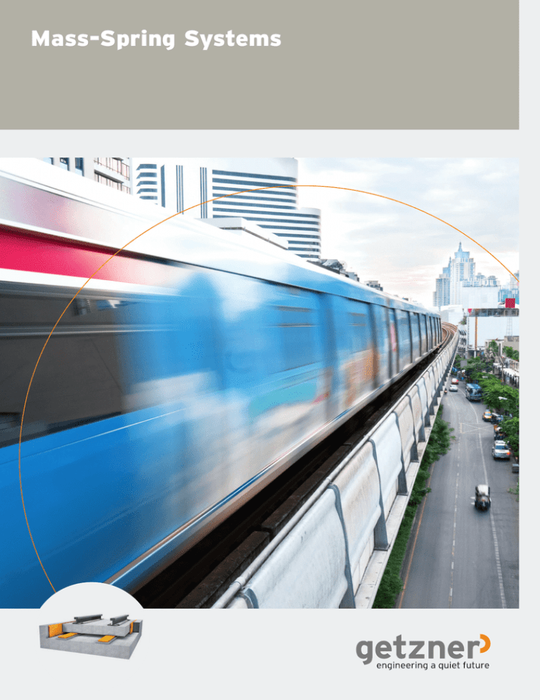
Mass-Spring Systems 1 Structure-Borne Noise and Its Consequences Calm sets in Road traffic and trains cause structure-borne noise due to their speed and weight. This noise spreads out through the ground and causes vibrations in buildings and nearby machines or sensitive measurement equipment. uildings, equipment and machines are themselves systems capable of vibration. Excitation by trains or traffic is amplified by the structure of the buildings and objects affected. The mechanical vibrations and the resulting secondary air-borne sound, in other words noise, are harmful to humans in the case of long-term exposure. B Vibrations also influence the functioning of machines and equipment, in some cases significantly impairing their operation or negatively influencing quality and productivity. In addition, dynamic overloading of the building structure poses the risk of damage to the building, such as subsiding and cracks. 3 2 Highly Effective Structure-Borne Noise Protection Effective over decades 4 tructure-borne sound emissions can be reduced at their point of origin through various measures tailored to the specific requirements. Mass-spring systems are used in situations where the highest demands are placed on structure-borne sound protection. The materials Sylomer® and S Sylodyn® are used throughout the world as individual, elastic supports. They guarantee the required effectiveness for decades. Combined with Getzner’s technical know-how, these proven materials are now considered to be the standard high-tech solution for mass-spring systems. Advantages of Sylomer ® and Sylodyn ® supports Sylomer® and Sylodyn® are the ideal materials for use as highly elastic supports in a mass-spring system – whatever the construction method. — Reliable, homogenous and lasting elasticity — Short-term, even extreme, overloading is possible — Can be directly driven over by heavy vehicles — Low construction costs thanks to simple and fast installation — Various shapes are possible by varying the density, thickness and loaded area of the material — High efficiency and long-term stability — Minimal maintenance expenses 5 3 How a Mass-Spring System Functions Effectively isolating vibrations The goal of vibration isolation is to dynamically decouple the superstructure from its environment in order to reduce the transmission of vibrations and structure-borne sound. Fe(t) his decoupling is achieved by creating a system capable of vibration. If a permanently elastic spring layer, such as Sylomer® or Sylodyn®, is installed, the isolation takes place directly at the source of the emissions. This ensures that the support point force Fu(t) is smaller than the exciter force Fe(t), resulting in reduced vibrations produced by the support point forces. T m c d Fu(t) he function of an elastically supported superstructure can be described very easily using an alternate system, referred to as a single degree of freedom system. Many vibration problems can be approximately explained with this simple physical model. If the superstructure mass is brought out of equilibrium by a brief exciter force Fe(t), the mass executes vibrations with the natural frequency f0. T 6 c = dynamic spring stiffness m = superstructure mass + unsprung mass of wheelset he speed with which these vibrations decrease in amplitude depends on the damping of the spring. For Sylomer® and Sylodyn® materials, the damping is described by the mechanical loss factor. Two areas exist in the vibration isolation system, namely an amplification area and an isolation area. T Load transmission factor VR The amplitude frequency response (amount of transmission function) must be determined in order to evaluate a mass-spring system. This describes the amplitude relationship based on the frequency f or based on the frequency relationship between the support point force Fu(t) and the exciter force Fe(t) in the case of source isolation. 3.0 0.2 0 The amplification only occurs if an exciter frequency is present that matches the natural frequency of the elastic support or in the case of broadband stimulation. The isolation starts at a frequency that corresponds to 2•f0. The amplitude frequency response indicates that the amplification at the insulator natural frequency f0 is reduced with an increas- 0.1 0 2.5 0.3 2.0 ing level of damping, while the level of isolation decreases with increasing damping. In terms of the properties of the spring in a mass-spring system, this means that the system must have the lowest possible ratio of dynamic to static stiffness. The dynamic stiffness of the support should also only be subject to minor changes due to frequency and load. The dimensioning of a mass-spring system is an optimization problem for engineers. This problem requires in-depth and specialized knowledge, which Getzner has offered with its partners for years. The functioning of a mass-spring system can, however, be greatly affected by standing water under the mass trough and within the system. When installing a mass-spring system, it is therefore essential to ensure sufficient long-term drainage. 0.5 1.5 0.8 1.0 =1.0 0.8 0.3 0.2 0.5 0.5 0.1 Amplification Isolation 0.0 0.3 0.4 0.6 0.8 1 2 2 3 4 5 6 7 8 Tuning ratio 7 4 Design Variants A number of different designs have been developed by European railway companies for mass-spring systems in recent decades. For instance, there are designs with either in-situ casted or prefabricated concrete slabs as well as combinations of the two, both with and without ballast beds. n designing an elastic support for mass-spring systems, the selected construction method is also important for the functionality and economic efficiency of the overall system. I Whether full-surface, linear or pointlike support – Getzner’s know-how ensures technically faultless, economically sustainable and functional solutions. 8 Full-surface support Linear support Point-like support Full-surface support Linear support Point-like support epending on the specific application, a full-surface elastic support achieves natural frequencies in the range of 14-25 Hz. This corresponds to an achievable structure-borne noise damping of up to 30 dB in the supercritical frequency range. inear supports are preferred in mass-spring systems that make use of prefabricated elements or combine prefab with in-situ casted concrete. The horizontal forces that arise both in the direction of travel (braking and acceleration forces) as well as perpendicular to the track axis (e.g. centrifugal forces, side forces resulting from track geometry errors) can be handled well by the relatively large support surfaces. T D A full-surface elastic support from Getzner offers advantages in the following areas: — Simple, fast and inexpensive construction methods — Low risk of construction errors — Wide-area load distribution in the subsoil — Damping of structural vibrations of the track support elements — Low number of installation joints — High horizontal stability of the entire system — Economy of the entire system L With linear support, it is possible to achieve lower support structure natural frequencies (8-15 Hz) than with full-surface support while keeping expenses reasonable. Overall, linear support achieves a higher damping of structure-borne sound. he selected construction method for the track support slabs or track troughs determines the type of point-like support. Generally it is used with track support slabs created using site-mixed concrete and lifted into place after hardening. The supports are inserted through openings in the plate. Since train operations give rise to horizontal forces, attention must be paid to the transmission of these forces during dimensioning of the generally relatively small support surfaces. In order to limit the horizontal deflections in line with the requirements, the optimal values for shear modulus, support layer thickness and support area are used in practice. The lowest natural frequencies are achievable with point-like supports (5-12 Hz). This type of support satisfies the highest requirements for structure-borne sound protection. Structure-borne sound damping of 30 dB and more can be achieved with this type of system. 9 5 Design of Elastically Supported Transitions For a smooth transition he transition areas between neighboring superstructure types (ballasted track, slab track) must be planned very precisely in order to prevent lasting flaws in the track. Transition areas always arise for massspring systems since these are accompanied by higher deflection than normal superstructures. Due to temperature fluctuations and concrete deterioration, the transition areas are also subject to special loads. Getzner offers competent solutions in this area as well. T For example, the required system stiffness in the transition structures can be achieved in the following ways: (FEA), Getzner calculates and simulates all factors for the optimal design of transition areas. — Compressed support arrangement — Change to the support material stiffness — Installation of special rail fastenings — Installation of undersleeper pads The fact that excessive support point forces can overload a rail fastening must be considered during implementation. Using finite element analysis Transition between mass-spring system and slab track with elastic undersleeper pads. Ballasted track 10 Slab track 11 6 Construction Errors Our experience gives you security onstruction or design errors and improper or absent features can in some cases affect the real properties of mass-spring systems. C Examples include: — Insufficient or absent drainage resulting in a “stamp effect” within the system — For full-surface systems: absent, unsuitable or excessively stiff side mats — Faulty isolation of cable shafts, drainage inlets and other connections — Unsuitable support material or support layer thicknesses below specific minimums — Large number of installation joints — Improper, careless installation of the support material — Structural design, such as the length of the deck slab or design of the reinforcement, insufficient load distribution on the elastomer xecution flaws in a mass-spring system can generally only be corrected later at great expense and effort. Depending on the severity of the flaws, it is sometimes necessary to completely rebuild the track. E 12 7 Requirements for an Elastomer Support Multi-faceted and proven or more than four decades, the materials Sylomer® and Sylodyn® have proven themselves to be an effective protection against vibrations and structure-borne sound in railway superstructures. F Getzner materials contribute to the protection of structures, improve the stability of railway tracks and reduce the dynamic load on the ballast, thereby lowering maintenance expenses as well. Even after more than 30 years, railway applications made of Sylomer® and Sylodyn® remain effective. When samples were removed and tested, the elastomer showed no fatigue even after many years of operation. Conditions for functioning and long-lasting massspring systems: Especially with partial surface support, it is particularly important to define the requirements for the support material and the quality monitoring on a project-specific basis. — Further tests determine the extent to which the track geometry changes due to creeping, operating loads and environmental influences. — The static and dynamic stiffnesses must be evaluated in order to determine the specifically required properties of the support. — Changes to the specific support properties due to operating loads are tested with long-term vibration tests consisting of at least three million load changes. — Changes to the support properties due to environmental influences (e.g. ozone, water, oils, chemicals) must also be evaluated. — The quality of the support is carefully monitored even before installation. he standard DIN 45673-7, Mechanical vibration – Resilient elements used in railway tracks – Part 7: Laboratory test procedures for resilient elements of mass-spring-systems, provides additional information on suitability for use and testing of the static-dynamic stiffnesses. T 13 8 Finite Element Analysis 14 Finite element analysis yields the following results: Know what you are dealing with — Support capacity of the support slab — Static deformation due to dead weight substitute physical system consisting of mass relationships, stiffnesses and damping coefficients must always be developed for a system analysis. The most well-known system analysis method is finite element analysis (FEA). A — Natural modes — Natural frequencies — Strength information — Dynamic loading and vibration movements In vibration isolation, it is generally assumed that the vibration-isolated object (the support slab of the track) and the subsoil are each rigid bodies. The purpose of this assumption is to verify the effect of the vibration isolation by way of simulation. However, if one wishes to identify limitations and understand the total behavior of the system, additional degrees of freedom that are relevant to the real system are identified and analyzed using FEA. — System behavior under defined stimulation — Prediction of the dynamic behavior of a system for various system parameters he design requirements are constantly growing. Getzner offers a wide range of services as a competent partner to planners and engineers working on this complex subject. T — Required modifications for a desired dynamic behavior 15 9 Installation Information 16 Isolation of a mass-spring system against drains Preparatory measures Delivery Laying hen installing, it is important to ensure that the Sylomer® or Sylodyn® support layer completely decouples the subsequently laid support slab from the environment. Sound bridges can prevent functional vibration isolation. It is also important to ensure drainage of the system. etzner delivers the materials directly to the construction site: side mats, linear supports and discrete supports on pallets, ground mats as rolled sheets with a standard width of 1.50 m. Depending on the geometry and installation conditions, Getzner assembles the mats at the factory, allowing fast and economical installation on-site. etzner always pays attention to the total weight when assembling the rolls. This means that the mats can easily be laid by a two-man team. In this way, it is possible to lay over 500 m2 per person each day. Linear and discrete supports can even be positioned by a single person. The mat length or protruding corners can be easily corrected by the person laying the mats using disposable knives. W The subsoil must therefore be flat and free of pointed or sharp objects. If this is only possible to a limited extent, it is possible, for example, to lay a fleece between the subsoil and the mat to protect the support layer. A sub-base of concrete has also proven effective. Special discrete bearings must be stable and accurately positioned. A corresponding base with a steel frame represents one effective option. G The ground mats can be laid both parallel and perpendicular to the track axis. It is important here to keep the number of joints to a minimum. The remaining joints are sealed with tape to prevent the concrete mixture from entering and creating structure-borne sound bridges. G If desired, Getzner will create professional installation plans or provide a construction supervisor to guarantee proper installation. Reinforcement may be useful for a full-surface solution. In this case, sufficient load distribution from the reinforcement to the Sylomer® or Sylodyn® mats must be ensured. Corresponding supporting surfaces (wood or plastic panels) prevent excessive surface compression or deflections. 17 10 International References etzner solutions can be found around the world – as can Getzner experts. With our 10 branch ofices, we have a local presence in important geographic regions. We serve practically all of the relevant markets in the world with our numerous sales partners. G Branches in: — — — — — — — — — — Bürs, Austria Berlin, Germany Munich, Germany Stuttgart, Germany Lyon, France Amman, Jordan Tokyo, Japan Pune, India Beijing, China Charlotte, USA Getzner branch offices Getzner sales partners Reference countries 18 Milan tram line Nottingham tram line rojects realized by Getzner speak for themselves. Here is a sampling of our reference list in the railway sector: Standard-gauge railway Tram lines Select projects: — Brenner rail axis, northern approach line Brenner Zulauf Nord, Römerberg Tunnel, Zammer Tunnel, Arlberg Tunnel, New Lainz Tunnel, Sittenberg Tunnel (ÖBB) — Leipzig City Tunnel Old Mainz Tunnel New Mainz Tunnel City Tunnel Leipzig, Alter Mainzer Tunnel, Neuer Mainzer Tunnel, Tiergarten Tunnel, Berlin North-South, Lehrter Bahnhof (train station), Amperbrücke (bridge), Cologne/Bonn airport connection, Siegauen Tunnel, Audi Tunnel Ingolstadt (DB AG) — NEAT: Zurichberg Tunnel, Zimmerberg Tunnel (SBB) — Rome-Fiumicino, Udine-Tarvisio, Milan-Saronno, Catania (FS) — Channel Tunnel Rail Link (Network Rail) — Brussels (SNCB) — Augsburg — Barcelona — Berlin — Bern — Bordeaux — Brest — Constantine — Essen — Florence — Geneva — Gothenburg — Graz — Grenoble — Isfahan — Le Mans — Linz — Lyon — Madrid — Marseille — Mashhad P Munich underground line — Milan — Montpellier — Munich — Nantes — Nice — Nottingham — Orléans — Paris - St. Denis — Paris - T1 — Prague — Rome — Rouen — Santo Domingo — Seville — Shiraz — Strasbourg — Stuttgart — Tenerife — Valencia — Vienna Underground/ rapid transit lines — — — — — — — — — Athens Augsburg Berlin Bochum Buenos Aires Dortmund Düsseldorf Hong Kong Incheon — Krakow — Milan — Munich — New York — Nuremberg — Sao Paulo — Vienna — Zurich 19 Getzner Werkstoffe GmbH Am Borsigturm 11 13507 Berlin Germany T +49-30-405034-00 F +49-30-405034-35 info.berlin@getzner.com Getzner Werkstoffe GmbH Nördliche Münchner Str. 27a 82031 Grünwald Germany T +49-89-693500-0 F +49-89-693500-11 info.munich@getzner.com Getzner Spring Solutions GmbH Gottlob-Grotz-Str. 1 74321 Bietigheim-Bissingen Germany T +49-7142-91753-0 F +49-7142-91753-50 info.stuttgart@getzner.com Getzner France S.A.S. Bâtiment Quadrille 19 Rue Jacqueline Auriol 69008 Lyon France T +33-6 77 59 51 65 info.lyon@getzner.com Getzner Werkstoffe GmbH Middle East Regional Office Abdul - Hameed Sharaf Str. 114 Rimawi Center - Shmeisani P. O. Box 961 303 Amman 11196, Jordan T +9626-560-7341 F +9626-569-7352 info.amman@getzner.com Getzner India Pvt. Ltd. 1st Floor, Kaivalya 24 Tejas Society, Kothrud Pune 411038, India T +91-20-25385195 F +91-20-25385199 Nihon Getzner K.K. 6-8 Nihonbashi Odenma-cho Chuo-ku, Tokyo 103-0011, Japan T +81-3-6842-7072 F +81-3-6842-7062 info.tokyo@getzner.com Beijing Getzner Trading Co.; Ltd. Zhongyu Plaza, Office 1806 Gongti Beilu Jia No. 6 100027 Beijing, PR China T +86-10-8523-6518 F +86-10-8523-6578 info.beijing@getzner.com Getzner USA, Inc. 8720 Red Oak Boulevard, Suite 528 Charlotte, NC, 28217, USA T +1-704-966-2132 info.charlotte@getzner.com www.getzner.com B MFS Trams en © Copyright by Getzner Werkstoffe GmbH | 05-2015 Getzner Werkstoffe GmbH Herrenau 5 6706 Bürs Austria T +43-5552-201-0 F +43-5552-201-1899 info.buers@getzner.com
