AE-429-12
advertisement

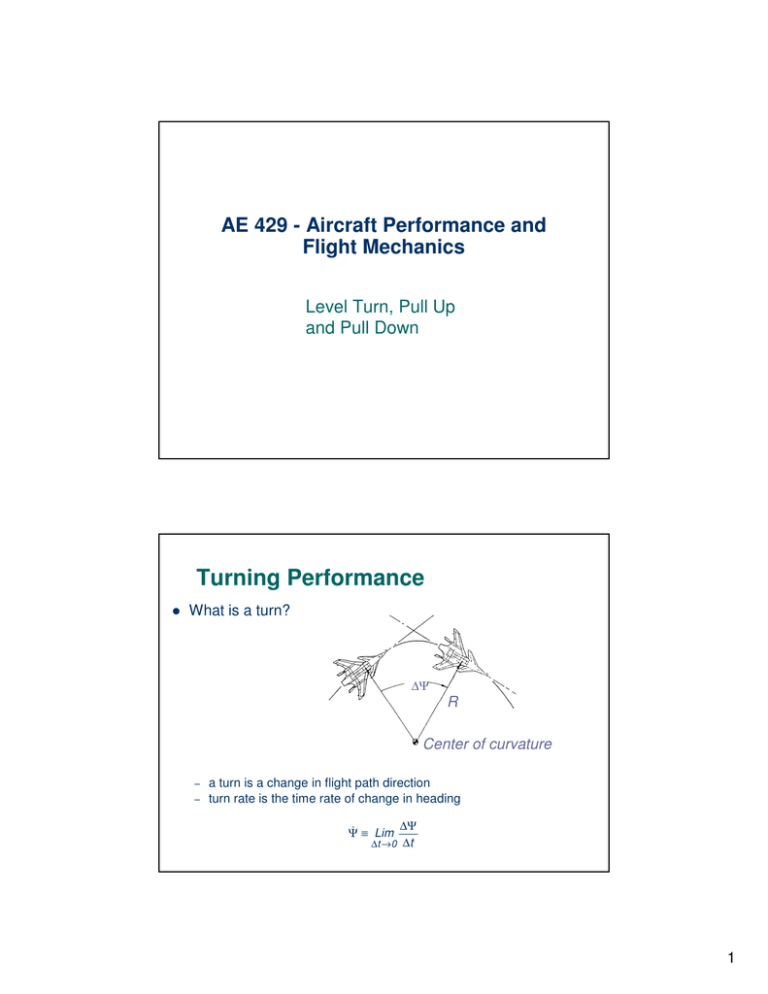
AE 429 - Aircraft Performance and Flight Mechanics Level Turn, Pull Up and Pull Down Turning Performance What is a turn? ∆Ψ R r Center of curvature – – a turn is a change in flight path direction turn rate is the time rate of change in heading Ψ ≡ Lim ∆Ψ ∆t → 0 ∆t 1 Turning Performance More definitions – Turn radius, R, is the distance between the flight path and the instantaneous center of curvature Lcos φ Load factor and turn radius – Lsin φ L φ Load factor n is defined as n≡ L W mV∞2 / R R In a level, un-accelerated turn W = L cos φ L 1 = n≡ W cos φ – N is a function of φ (bank angle) only in a steady, level turn – cos φ = W / L = 1/( L / W ) = 1/ n W φ = arccos(1/ n) for level turn, constant altitude L cos φ = W Perpendicular to flight path in the horizontal plane r2 = R 1 m (V∞ cosθ ) 2 r2 = L sin φ + T sin ε sin φ 0 Performance parameters: Turn radius R Turn rate ω = ψ dψ / dt local angular velocity along the curved flight path Larger the magnitude of Fr : tighter and faster will be the turn Note: L and φ are not independent in level turn 2 Turn Radius (V ) m ∞ 2 = L sin φ R R=m V∞2 W V∞2 1 V∞2 = = L sin φ L g sin φ n g sin φ cos φ = 1/ n cos2 φ + sin 2 φ = 1 1/ n2 + sin 2 φ = 1 sin 2 φ = 1 − 1/ n2 sin φ = 1 − 1/ n2 V∞2 V∞2 1 = R= n g 1 − 1/ n2 g n2 − 1 Small R Turn Rate R= ω = dψ / dt = V∞ / R V∞2 ω= g n2 − 1 high ω high n (large L/W) low Velocity dψ V∞ g n2 − 1 = = dt R V∞ high n (large L/W) low Velocity High Performance: smallest R and largest ω for largest n ; lowers speed V what is the higher possible n ? R and ω are function of n and V φ L n= 1 cos φ Level turn: nmax D TR but T < Tmax A implying that for Tmax A nmax = 1 1 = cos φmax cos φTA max L = n W = ½ ρ V2 S CL D = T; 1 ρV 2 S T 2 = K (W / S ) W Do not depend on W/S, T/W, k, Cd0, ρ L/D = n W/T − max CD0 1 ρV 2 2 W /S 1/ 2 = L T DW T= 1 2nW ρV 2 S CD0 + K 2 ρV 2 S 1 ≤ n ≤ nmax max φTmax A nmax = 2 C 1 ρV 2 L max 2 W /S 3 Minimum Turn Radius Minimum turn radius – Stall speed in straight and level flight (L = W) is Vs = – 2W ρ∞SCLmax In a level turn, stall speed becomes (L=nW) 2 nW ρ∞SCLmax Vsturn = Vsturn = Vs n – Which suggests that – Replacing Vs with Vsturn in the turn radius equation gives the aerodynamic limit on minimum turn radius Rmin = Vs2 turn g n2 − 1 = Vs2 n g n2 − 1 = Vs2 1 g 1− 2 n Level Turn Chart 4 Pull-Up Consider a turn in the vertical plane: winglevel Pull-Up (instantaneous turn) – – Different from level turn (constant flight properties) The radial forces are: at t = 0; θ = 0 Fr = L − W = W ( n − 1) R V 2 W V∞2 =m ∞ = R g R – Solving for R: R= – θ L>W V∞2 g (n − 1) θ=0 L=W And for turn rate: W g ( n − 1) V ω= ∞ = R V∞ W Pull-Down Now, look at another instantaneous turning maneuver in the vertical plane -- a “split s” – Using the same approach as for a Pull-Up at t = 0; θ = 0 m V∞2 = L +W R R= ω= – R=m V∞2 L +W W V∞2 g (n + 1) g (n + 1) V∞ The rate is improved and the radius is enlarged over pull-ups L R θ 5 Limiting cases: n large Effect of W/S (wing loading) and Clmax – When n is large, n +1 ≈ n −1 ≈ n V∞2 = V2 gn R ≈ ∞ , ω≈ gn V∞ 2L ρ∞SCL – Recalling that – Substituting, we obtain radius and rate of turn R= 2L ρ∞SCL g (L / W ) ω= gn 2L ρ∞SCL R= 2 W ρ∞CL g S ω=g ρ∞CL n 2W S ( ) For minimum turn radius and maximum turn rate – Maximize both CL and load factor Rmin = – 2 W ρ∞ gCLmax S ωmax = g ρ∞CLmax nmax 2W S ( ) Practical constraints on load factor – nmax is a function of CLmax; – at low speeds it will be limited by the aerodynamic lifting capability (stall) of the lifting surfaces nmax = – – CL 1 ρ∞V∞2 max W 2 S at high speeds, structural loads on the airframe may also limit nmax for many airplanes, the other force balance (T = D) governs the minimum turn radius and the maximum turn rate -- turn performance is limited by available thrust 6 constraints on V V as small as possible for Rmin and ωmax – L = n W = ½ ρ V2 S CL V∞ = – R= 2nW VStall = Rmin does not necessarily correspond to nmax V∞2 g n2 − 1 Rmin = CL = CL max ρ∞ SCL = 2q∞ g ρ∞ n 2 − 1 ∂R =0 ∂q∞ 2nW ρ∞ SCL max 1 ≤ n ≤ nmax 4k (W / S ) g ρ ∞ (T / W ) 1 − 4kCDo /(T / W )2 ωmax = q∞ ρ ∞ /(W / S )[(T / W ) /(2k ) − (CDo / k )1/ 2 ] nR min = 2 − 4kCDo /(T / W )2 V∞ R min = 4k (W / S ) /( ρ∞ (T / W )) V-n diagram the V-n diagram illustrates 2 of these constraints CL max Corner Velocity or maneuver velocity V* = 2nmax W ρ∞ CL max S 7 Aerodynamic and structural limits on turn performance Aerodynamic and thrust limits on turn performance Aerodynamics Wing Design nmax = CL 1 ρ∞V∞2 max W 2 S Thrust Available Drag Structural (Materials/ Wing Size) 8


