Measuring magnetic field using a search coil
advertisement
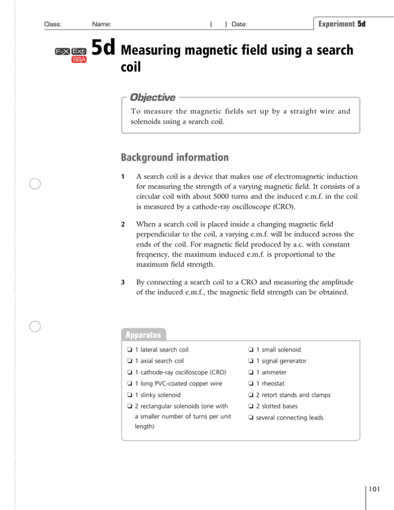
Class: Name: ( Experiment 5d ) Date: 5d Measuring magnetic field using a search coil Objective To measure the magnetic fields set up by a straight wire and solenoids using a search coil. Background information 1 A search coil is a device that makes use of electromagnetic induction for measuring the strength of a varying magnetic field. It consists of a circular coil with about 5000 turns and the induced e.m.f. in the coil is measured by a cathode-ray oscilloscope (CRO). 2 When a search coil is placed inside a changing magnetic field perpendicular to the coil, a varying e.m.f. will be induced across the ends of the coil. For magnetic field produced by a.c. with constant freqnency, the maximum induced e.m.f. is proportional to the maximum field strength. 3 By connecting a search coil to a CRO and measuring the amplitude of the induced e.m.f., the magnetic field strength can be obtained. Apparatus ❏ 1 lateral search coil ❏ 1 small solenoid ❏ 1 axial search coil ❏ 1 signal generator ❏ 1 cathode-ray oscilloscope (CRO) ❏ 1 ammeter ❏ 1 long PVC-coated copper wire ❏ 1 rheostat ❏ 1 slinky solenoid ❏ 2 retort stands and clamps ❏ 2 rectangular solenoids (one with ❏ 2 slotted bases a smaller number of turns per unit ❏ several connecting leads length) New Physics at Work (Second Edition) © Oxford University Press 2007 101 Experiment 5d Class: Name: ( ) Date: Procedure Straight wire 1 Set up a lateral search coil and connect it to a CRO (Fig 5d-1). cathode-ray oscilloscope (CRO) ✐ A signal generator of frequency of 5 kHz gives an induced e.m.f. of much larger value than a low voltage power supply. lateral search coil ✐ A large current is used in order to produce a large e.m.f. However, the rheostat commonly found in school can withstand a maximum current of 5 A only. Note This ensures that the search coil is perpendicular to the magnetic field. ✐ The resultant trace in CRO is not sharp due to the noise signal from surroundings. Switch off projector or other sources which may produce noise signal. Fig 5d-1 2 (a) Connect a long PVC-coated copper wire in series with a rheostat, an ammeter and a signal generator (Fig 5d-2). (b) Switch on the signal generator. Set the output voltage to 0–6 V of frequency 5 kHz in sine wave. (c) Place the search coil near one side of the wire. Adjust the time base of the CRO until a waveform is shown on the CRO screen clearly. Rotate the orientation of the search coil until the amplitude of the induced e.m.f. shown on the CRO screen is maximum. signal generator long PVC-coated copper wire ✐ The following methods can increase the sensitivity of the search coil: rheostat ammeter 1 Increase the number of turns of the search coil. lateral search coil 2 Increase the area of the search coil. 3 Use alternating current of higher frequency. (By increasing the frequency, the magnetic field changes with a faster rate. Therefore, the induced e.m.f. increases.) 102 cathode-ray oscilloscope (CRO) Fig 5d-2 New Physics at Work (Second Edition) © Oxford University Press 2007 Class: Name: ( 3 Place the search coil at different distances from the wire and take the amplitude of the induced e.m.f. shown on the CRO screen. Record the results in Table 5d-1. ✎ Results: Distance from wire r / cm Experiment 5d ) Date: 2 3 4 5 6 7 1 1 ( ) / cm–1 Distance r 0.50 0.33 0.25 0.20 0.17 0.14 Amplitude of induced e.m.f. / V (∝ magnetic field strength B) 0.235 0.165 0.130 0.110 0.095 0.085 Table 5d-1 4 1 . Record the results in Table 5d-1. r (b) Plot a graph of the amplitude of induced e.m.f. (directly 1 proportional to the magnetic field strength B) against in r Figure 5d-3. (a) Calculate the value of amplitude of induced e.m.f. / V (u magnetic field strength B) 0.30 0.25 0.20 0.15 0.10 0.05 0 0.1 0.2 0.3 0.4 0.5 0.6 1 ( 1 ) / cm–1 distance r Fig 5d-3 ✎ How is the magnetic field strength B related to the distance r from the wire? The magnetic field strength is inversely proportional to the distance from the wire, i.e. 1 B∝ . r New Physics at Work (Second Edition) © Oxford University Press 2007 103 Experiment 5d Class: ✐ The reading of a current smaller than 0.5 A should not be taken since the amplitude of noise signal may be comparable to the induced e.m.f. Name: ( 5 (a) Place the search coil at a fixed distance from the wire. (b) Vary the current flowing through the wire by changing the resistance of the rheostat. (c) Take the ammeter reading and the amplitude of the induced e.m.f. shown on the CRO screen. Record the results in Table 5d-2. 6 Repeat several times with other current values through the wire. Record the results in Table 5d-2. ✎ Results: Current through wire I / A 0.5 Amplitude of induced e.m.f. / V (∝ magnetic field strength B) ) Date: 0.6 0.120 0.145 0.7 0.8 0.9 0.170 0.193 0.215 Table 5d-2 7 Plot a graph of the amplitude of induced e.m.f. (directly proportional to the magnetic field strength B) against the current I through wire in Figure 5d-4. amplitude of induced e.m.f. / V (u magnetic field strength B) 0.30 0.25 0.20 0.15 0.10 0.05 0 0.2 0.4 0.6 0.8 1.0 current through wire I / A Fig 5d-4 ✎ How is the magnetic field strength B related to the current I through the wire? The magnetic field strength is directly proportional to the current through the wire, i.e. B ∝ I. 104 New Physics at Work (Second Edition) © Oxford University Press 2007 Class: Name: ( Experiment 5d ) Date: Slinky solenoid 8 (a) Set up an axial search coil and connect it to a CRO. (b) Connect a slinky solenoid in series with a rheostat, an ammeter and a signal generator (Fig 5d-5). signal generator ammeter rheostat cathode-ray oscilloscope (CRO) slinky solenoid axial search coil Fig 5d-5 9 Place the search coil at different positions inside the slinky solenoid and note any change in the amplitude of the induced e.m.f. shown on the CRO screen. ✎ How does the magnetic field strength (directly proportional to the amplitude of induced e.m.f.) change inside the slinky solenoid? The magnetic field strength does not vary inside the slinky solenoid. ✐ However, the magnetic field strength decreases significantly at the two ends of the slinky solenoid. Ts may tell Ss to check this out. 10 (a) Place the search coil at a fixed position inside the slinky solenoid. (b) Vary the current flowing through the slinky solenoid by changing the resistance of the rheostat. (c) Take the ammeter reading and the amplitude of the induced e.m.f. shown on the CRO screen. Record the results in Table 5d-3 on p.106. New Physics at Work (Second Edition) © Oxford University Press 2007 105 Experiment 5d Class: Name: ( ) Date: 11 Repeat several times with other current values through the slinky solenoid. Record the results in Table 5d-3. Results: ✎ Current through slinky solenoid I / A Amplitude of induced e.m.f. / V (∝ magnetic field strength B) 0.2 0.4 0.012 0.022 0.6 0.8 1.0 0.032 0.042 0.052 Table 5d-3 12 Plot a graph of the amplitude of induced e.m.f. (directly proportional to the magnetic field strength B) against the current I through slinky solenoid in Figure 5d-6. amplitude of induced e.m.f. / V (u magnetic field strength B) 0.06 0.05 0.04 0.03 0.02 0.01 0 0.2 0.4 0.6 0.8 1.0 current through slinky solenoid I / A Fig 5d-6 ✎ How is the magnetic field strength B related to the current I through the slinky solenoid? The magnetic field strength is directly proportional to the current through the slinky solenoid, i.e. B ∝ I. 13 (a) Place the search coil at a fixed position inside the slinky solenoid. 106 (b) Vary the length of the slinky solenoid. New Physics at Work (Second Edition) © Oxford University Press 2007 Class: Name: ( Experiment 5d ) Date: (c) Measure the length of the slinky solenoid and take the amplitude of the induced e.m.f. shown on the CRO screen. Record the results in Table 5d-4. 14 Repeat several times with other lengths of the slinky solenoid. Record the results in Table 5d-4. ✎ Results: Length of slinky solenoid l / m 1.0 0.9 0.8 0.7 0.6 1 1 ( ) / m–1 Length l 1.00 1.11 1.25 1.43 1.67 Amplitude of induced e.m.f. / V (∝ magnetic field strength B) 0.043 0.047 0.052 0.059 0.068 Table 5d-4 1 . Record the results in Table 5d-4. l (b) Plot a graph of the amplitude of induced e.m.f. (directly 1 proportional to the magnetic field strength B) against in l Figure 5d-7. 15 (a) Calculate the value of amplitude of induced e.m.f. / V (u magnetic field strength B) 0.06 0.05 0.04 0.03 0.02 0.01 0 0.5 1.0 1.5 1 ( 1 ) / m–1 length l Fig 5d-7 New Physics at Work (Second Edition) © Oxford University Press 2007 107 Experiment 5d Class: Name: ✎ ( ) Date: How is the magnetic field strength B related to the length l of the slinky solenoid? The magnetic field strength is inversely proportional to the length of the slinky 1 solenoid, i.e. B ∝ . l Rectangular solenoid 16 Connect a rectangular solenoid in series with a rheostat, an ammeter and a signal generator (Fig 5d-8). signal generator solenoid rheostat ammeter axial search coil cathode-ray oscilloscope (CRO) Fig 5d-8 17 Place the search coil at different positions inside the solenoid and note any change in the amplitude of the induced e.m.f. shown on the CRO screen. ✎ The magnetic field strength does not vary inside the solenoid. ✐ However, the magnetic field strength decreases significantly at the two ends of the solenoid. Ts may tell Ss to check this out. 108 How does the magnetic field strength (directly proportional to the amplitude of induced e.m.f.) change inside the solenoid? 18 (a) Place the search coil at a fixed position inside the solenoid. (b) Vary the current flowing through the solenoid by changing the resistance of the rheostat. (c) Take the ammeter reading and the amplitude of the induced e.m.f. shown on the CRO screen. Record the results in Table 5d-5 on p.109. New Physics at Work (Second Edition) © Oxford University Press 2007 Class: Name: ( ) Date: Experiment 5d 19 Repeat several times with other current values through the solenoid. Record the results in Table 5d-5. ✎ Results: Current through solenoid I / A Amplitude of induced e.m.f. / V (∝ magnetic field strength B) Table 5d-5 20 Plot a graph of the amplitude of induced e.m.f. (directly proportional to the magnetic field strength B) against the current I through solenoid in Figure 5d-9. amplitude of induced e.m.f. / V (u magnetic field strength B) current through solenoid l / A Fig 5d-9 ✎ How is the magnetic field strength B related to the current I through the solenoid? The magnetic field strength is directly proportional to the current through the solenoid, i.e. B ∝ I. 21 (a) Place the search coil at a fixed position inside the solenoid and note the amplitude of the induced e.m.f. shown on the CRO screen. New Physics at Work (Second Edition) © Oxford University Press 2007 109 Experiment 5d Class: Name: ( ) Date: (b) Repeat by using a rectangular solenoid with a smaller number of turns per unit length (Fig 5d-10) and of a smaller size (Fig 5d-11) in turn. solenoid of smaller size solenoid with smaller number of turns per unit length Fig 5d-10 ✎ Fig 5d-11 How does the magnetic field strength change with the number of turns per unit length and the size of the solenoid? The magnetic field strength increases with the number of turns per unit length of the solenoid. It does not change with the size of the solenoid. Discussion ✎ Where can a uniform magnetic field be detected for the two solenoids? A uniform magnetic field can be detected inside the two solenoids. 1 The strength of a varying magnetic field can be measured search coil using a ____________________________ . 2 The strength of the magnetic field set up by a current-carrying directly proportional straight wire is ________________________ to the current flowing inversely proportional through the wire and __________________________ to the distance from the wire. 3 The magnetic field set up by a current-carrying solenoid is uniform ______________________ inside the solenoid. It is directly proportional _______________________________ to the current flowing through increases the solenoid and _______________________________ with the number of turns per unit length of the solenoid. It is independent _______________________________ of the area of the solenoid. 110 New Physics at Work (Second Edition) © Oxford University Press 2007
