Mechanics 1.3.11-00 Projectile motion
advertisement

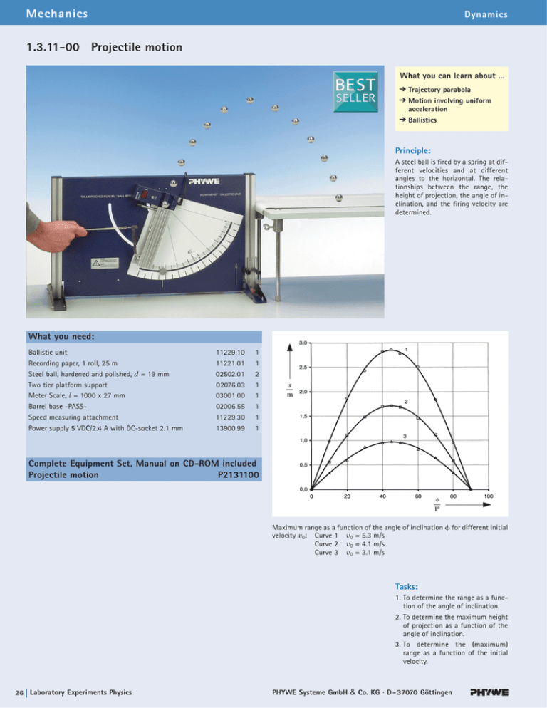
Mechanics Dynamics 1.3.11-00 Projectile motion What you can learn about … Trajectory parabola Motion involving uniform acceleration Ballistics Principle: A steel ball is fired by a spring at different velocities and at different angles to the horizontal. The relationships between the range, the height of projection, the angle of inclination, and the firing velocity are determined. What you need: Ballistic unit 11229.10 1 Recording paper, 1 roll, 25 m 11221.01 1 2 Steel ball, hardened and polished, d = 19 mm 02502.01 Two tier platform support 02076.03 1 Meter Scale, l = 1000 x 27 mm 03001.00 1 Barrel base -PASS- 02006.55 1 Speed measuring attachment 11229.30 1 Power supply 5 VDC/2.4 A with DC-socket 2.1 mm 13900.99 1 Complete Equipment Set, Manual on CD-ROM included Projectile motion P2131100 Maximum range as a function of the angle of inclination for different initial velocity v0: Curve 1 v0 = 5.3 m/s Curve 2 v0 = 4.1 m/s Curve 3 v0 = 3.1 m/s Tasks: 1. To determine the range as a function of the angle of inclination. 2. To determine the maximum height of projection as a function of the angle of inclination. 3. To determine the (maximum) range as a function of the initial velocity. 26 Laboratory Experiments Physics PHYWE Systeme GmbH & Co. KG · D - 37070 Göttingen LEP 1.3.11 -00 Projectile motion Related topics Trajectory parabola, motion involving uniform acceleration, ballistics. Principle A steel ball is fired by a spring at different velocities and at different angles to the horizontal. The relationships between the range, the height of projection, the angle of inclination, and the firing velocity are determined. Equipment Ballistic unit Recording paper, 1 roll, 25 m Steel ball, d = 19 mm Two-tier platform support Meter scale, demo, l = 1000 mm Barrel base Speed measuring attachement Power supply 5 VDC/2.4 A 11229.10 11221.01 02502.01 02076.03 03001.00 02006.10 11229.30 13900.99 1 1 2 1 1 1 1 1 Tasks 1. To determine the range as a function of the angle of inclination. 2. To determine the maximum height of projection as a function of the angle of inclination. 3. To determine the (maximum) range as a function of the initial velocity. Set-up and procedure The ballistic unit is adjusted. The scale is set to read 90 ° and a ball is fired upwards (setting 3) and is caught in the hand. The support base adjusting screws are turned until a vertical projection is obtained. The initial velocities of the ball corresponding to the three tension stages of the firing spring can be determined using the speed measuring attachment, or from the maximum height for a vertical projection from the expression v0 = 22gh . The inital velocities may vary greatly from unit to unit. The 2-tier platform support (02076.01) is used for determining the range. To mark the points of impact, the recording strip is secured to the bench with adhesive tape. It is best to measure the long ranges before the short ones (secondary impact points!) and to mark the primary impact points with a felt pen. The distance from the ballistic unit is frequently checked with the meter scale during the test. An empty box can be placed behind the bench to catch the balls. Fig. 1: Experimental set-up for measuring the maximum range of a projectile with additional equipment to measure the initial velocity. PHYWE series of publications • Laboratory Experiments • Physics • © PHYWE SYSTEME GMBH & Co. KG • D-37070 Göttingen P2131100 1 LEP 1.3.11 -00 Projectile motion Fig. 2: Movement of a mass point under the effect of gravitational force. Fig. 3: Maximum range as a function of the angle of inclination for different initial velocity v0: Curve 1 v0 = 5.3 m/s Curve 2 v0 = 4.1 m/s Curve 3 v0 = 3.1 m/s To measure the height of projection the meter scale is clamped in the barrel base and moved parallel to the plane of projection. The empty box is again used to catch the balls. The heights of projection can be determined ballistically quite well by eye. Theory and evaluation If a body of mass m moves in a constant gravitational field (gravitational force mg ), the motion lies in a plane. If the coordinate system is laid in this plane (x, y plane – see fig. 2) and the equation of motion: m From the regression line of the data of fig. 5, using the expression: Y = A · XB d2 S r 1t 2 m S g dt2 we obtain the exponent where: B = 2.01 = 0.001 r = (x,y) ; g = (0, – g) is solved, then, with the initial conditions r (0) = 0 v (0) = (v0 cos , v0 sin ) we obtain the coordinates as a function of time t: x 1t 2 v0 · cosf · t y 1t 2 v0 · sinf · t g 2 t : 2 From this, the maximum height of projection h is obtained as a function of the angle of projection : h v20 sin2 f 2g and the maximum range s is: s 2 v20 sin 2 f g P2131100 Fig. 4: Maximum height of projection h as a function of the angle of inclination for the initial velocities as in Fig. 1. PHYWE series of publications • Laboratory Experiments • Physics • © PHYWE SYSTEME GMBH & Co. KG • D-37070 Göttingen LEP 1.3.11 -00 Projectile motion Fig. 5: Maximum range s as a function of the inital velocity vo with a fixed angle of inclination = 45 °. Note To ensure an accurate determination of the initial velocity, the time taken for the ball to cover the measuring distance must be taken into account. If vexp is the experimentally determined inital velocity we obtain v0 2v2exp 2g d sin f where d is the distance between the point of rotation and the centre between the light barriers. PHYWE series of publications • Laboratory Experiments • Physics • © PHYWE SYSTEME GMBH & Co. KG • D-37070 Göttingen P2131100 3 LEP 1.3.11 -00 4 Projectile motion P2131100 PHYWE series of publications • Laboratory Experiments • Physics • © PHYWE SYSTEME GMBH & Co. KG • D-37070 Göttingen


