Non-piloted miniature pressure reducing valves type ADC, ADM
advertisement

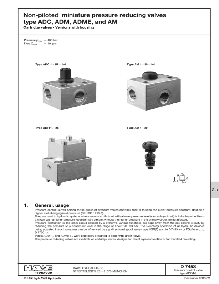
Non-piloted miniature pressure reducing valves type ADC, ADM, ADME, and AM Cartridge valves - Versions with housing Pressure pmax = 400 bar Flow Qmax = 10 lpm Type ADC 1 - 15 - 1/4 Type AM 1 - 20 - 1/4 Type AM 11. - 25 Type AM 1 - 20 2.3 1. General, usage Pressure control valves belong to the group of pressure valves and their task is to keep the outlet pressure constant, despite a higher and changing inlet pressure (DIN ISO 1219-1). They are used in hydraulic systems where a second oil circuit with a lower pressure level (secondary circuit) is to be branched from a circuit with a higher pressure level (primary circuit), without the higher pressure in the primary circuit being affected. Pressure fluctuation in the main circuit caused by a system‘s various functions are kept away from the pre-control circuit, by reducing the pressure to a consistent level in the range of about 20...30 bar. The switching operation of all hydraulic devices being actuated in such a manner can be influenced by e.g. directional spool valves type HSR(F) acc. to D 7493 ++ or PSL(V) acc. to D 7700 ++. Types ADM 1.. and ADME 1.. were especially designed to cope with larger flows. The pressure reducing valves are available as cartridge valves, designs for direct pipe connection or for manifold mounting. HAWE Hydraulik SE STREITFELDSTR. 25 • 81673 MÜNCHEN © 1991 by HAWE Hydraulik D 7458 Pressure control valve type ADC(M) December 2006-02 D 7458 page 2 2. Types available, main data Coding, Symbol max. pressure (bar) Inlet P Outlet A (Recomm. value) 2) pA * approx. 15% pE (bar) (bar) Screw-in cartridge Housing design for manifold for direct pipe mounting connection ADC 1 - 15 ADC 1 - 15 - 1/4 --- 18 ADC 1 - 25 ADC 1 - 25 - 1/4 --- 30 ADC 1 K - 25 1) ADC 1 K - 25 - 1/4 1) --- 25 AM 1 - 20 AM 1 - 20 - 1/4 --- 20 AM 1 - 25 AM 1 - 25 - 1/4 --- 25 --- --- AM 11 F - 5 5 --- --- AM 11 F - 10 10 --- --- AM 11 F - 15 15 --- --- AM 11 F - 20 20 AM 1 E - 20 AM 1 E - 20 - 1/4 AM 11 E - 20 20 AM 1 E - 25 AM 1 E - 25 - 1/4 AM 11 E - 25 25 AM 1 E - 30 AM 1 E - 30 - 1/4 AM 11 E - 30 30 AM 1 E - 35 AM 1 E - 35 - 1/4 AM 11 E - 35 35 AM 1 E - 40 AM 1 E - 40 - 1/4 --- 40 AM 1 D - 40 AM 1 D - 40 - 1/4 --- 40 AM 1 D - 45 AM 1 D - 45 - 1/4 --- 45 AM 1 D - 50 AM 1 D - 50 - 1/4 --- 50 AM 1 D - 55 AM 1 D - 55 - 1/4 --- 55 AM 1 D - 60 AM 1 D - 60 - 1/4 --- 60 AM 1 C - 60 --- AM 11 C - 60 60 AM 1 C - 70 --- AM 11 C - 70 70 AM 1 C - 80 --- AM 11 C - 80 80 AM 1 C - 90 --- AM 11 C - 90 90 AM 1 C - 100 --- AM 11 C - 100 100 --- ADM 1 - 15 --- 15 --- ADM 1 - 20 --- 25 --- ADM 1 - 30 --- 28 --- ADM 1 - 40 --- 40 --- ADM 1 - 50 --- 50 --- ADM 1 - 70 --- 70 ADME 1 - 15 ADM 1 K - 15 1) --- 15 ADME 1 - 20 --- --- 20 ADME 1 - 30 --- --- 30 ADME 1 - 50 --- --- 50 ADME 1 - 70 --- --- 70 1) Flow Sectional views and symbols (examples) Q A max (lpm) Type ADC 1 - 15 315 2 400 2 400 2 Type AM 1 - 20 - 1/4 400 2 400 2 400 2 Type AM 11 E - 25 315 8 315 10 315 8 Adjustable version (adjustment by means of tools, see section 4). The specified pressure pA represents the max. pressure setting, pmin approx. 5 bar 2) For notes regarding the pressure adjustment, see section 3 D 7458 page 3 3. Other characteristic data Designation Directly controlled pressure control valve with overdrive compensation Type Spool valve Material Screw-in cartridge: Screw nitrided Hole diamond-honed Regulator piston made of stainless steel (type ADC 1.., AM 1(11)..) bearing steel (type ADM..), case-hardened and polished. Bore and piston polish-deburred Control edges feature optimum resistance to wear caused by the erosion and cavitation effect of the fluid in flux. Zinc galvanized; This together with the nitrous hardened components ensures a good corrosion protection of the surface. Housing: Connection Cartridge valve: Housing version: Installation position Any Flow direction Operating direction Free return Over drive PortP and A R see table, pos. 2 max. 20 bar Leakage oil TypeADC 1(K) - .. = approx. 0.5 lpm at pE , 300 bar TypeAM 1(E, D, C) - .. ADM(E) 1- .. AM 11... = approx. 0.1 lpm at pE , 300 bar (depends largely on thread tolerance) Mass (weight) approx. g Type ADC 1 - .. ADC 1K - 25 AM 1 - .. AM 1E - .. AM 1D - .. AM 1C -.. Pressure fluid Temperature Mounting hole, see unit dimensions section 4.1 Direct pipe connection design (G 1/4 ISO 228/1 (BSPP) and DIN 3852 E) Manifold mounting design (hole pattern, see section 4.2) PdA AdP only permissible to limited extent, see |p-Q-characteristic AdT(R) see pA-QA curve below AM 11... ADM 1 - .. ADME 1 - .. Screw-in cartridge 30 45 30 70 --- --- 50 Housing design 320 340 340 380 200 350 --- Hydraulic fluid (DIN 51524 table 1 to 3); ISO VG 10 to 68 (DIN 51519) Viscosity range: min. 4; max. 800 mm2/sec; Optimal operation range: 10...200 mm2/sec Also suitable are biodegradable pressure fluids of the type HEPG (Polyalkylenglycol) and HEES (synth. Ester) at operation temperatures up to +70°C. Ambient: -40...+80°C Fluid: -25...+80°C, pay attention to the viscosity range! Start temperature down to -40°C are allowable (Pay attention to the viscosity range during start!), as long as the operation temperature during consequent running is at least 20K (Kelvin) higher. Biodegradable pressure fluids: Pay attention to manufacturer‘s information. With regard to the compatibility with sealing materials do not exceed +70°C. D 7458 page 4 pA - QA curve (tendency) of pA , 20 ... 25% of pA , 15 ... 20% of pA pA with table sect. 2 Oil viscosity during the measurement approx. 60 mm2/sec Overdrive Overdrive compensation occurs when the consumer is forced back against pA by an external force. In this case, the valve acts like a pressure limiting valve from AdT(R). Free return AdP A free return flow AdP is only possible, if the valve was previously unloaded, i.e. in the open idle position PdA (return flow must not exceed 1/3 of QA max ). A bypass check valve is required, when a return flow AdP is desired with minimized hindrance. Pressure adjustment via washers Type AM 1 E - 20...40 AM 1 D - 40...60 AM 11 E(F) - ... AM 1 C - ... AM 11 - ... ADM 1 - 20...30 ADME 1- 20...30 ADME 1- 50...70 Washer (HAWE-No.) 7625 525 (per washer 0.75 mm approx. |p = 5 bar) 7625 549 (per washer 0.4 mm approx. |p = 5 bar) 7434 006 a 0.5 mm 7434 006 b 1.0 mm 7434 006 c 2.0 mm (dep. on demand) D 7458 page 5 Dimensions of units All dimensions are in mm, subject to change without notice! Screw-in cartridge Type ADC 1K - 25 Mounting hole for type ADC 1 - .. and ADC 1K - 25 1) Torque 10 Nm Torque 10 Nm 10.5 to 12 Type ADC 1 - .. 1) Mounting hole for type AM 1 - 20(25), AM 1E(D, C) -.. Type AM 1 - 20(25) Type AM 1E(D, C) - .. 1) 1) Torque 7 Nm 1) ERMETO EOLASTIC-seal (coding: ED R 1/4”) a (mm) AM 1 E(D) AM 1 C 43.5 57.4 Mounting hole for type ADME 1 - .. Type ADME 1 - .. Sealing Cu A24x30x2 O-ring 15.55x2.62 NBR 90 Sh O-ring 12.37x2.62 NBR 90 Sh Teflon support ring 38 Reamed depth a/f 27 Torque 60 Nm Reamed depth 4.1 max. approx. 48 4. D 7458 page 6 4.2 Housing design Type ADC 1 - ... - 1/4 Type AM 1 - 20(25) - 1/4 AM 1 E(D, C) - .. - 1/4 AM 1 C - .. - 1/4 AM 1E(D) - .. - 1/4 AM 1 - 20(25) - 1/4 Thru-hole Thru-hole Ports A, P, and R = G 1/4 ISO 228/1 (BSPP) Ports A, P, and R = G 1/4 ISO 228/1 (BSPP) Type ADM 1 - ... and ADM 1 K - 15 Type AM 11 ... Hole #3, 2.5 deep for the assembly centering pin approx. 38 Port sealing via O-ring NBR 90 Sh: Thru-hole = 7.65x1.78 A P, R = 6.07x1.78 Type ADM 1 K - 15 AM 11 C - 60 ... AM 11 E - 60 ... 35 AM 11 F - 5... 20 Type ADM 1 - .. R and P Type aa/f ADM 1 - 15 ADM 1 - 20 ADM 1 - 30 15 ADM 1 - 40 ADM 1 - 50 ADM 1 - 70 21 Ports A, P, and T Torque G 1/4 ISO 228/1 (BSPP) 20 Nm 17 19


