DC Ammeter Shunts - Spectrum Industries Catalog
advertisement
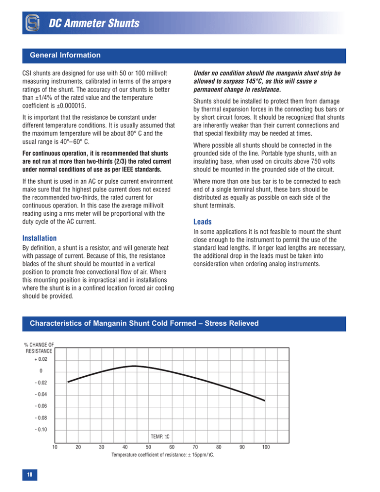
DC Ammeter Shunts General Information CSI shunts are designed for use with 50 or 100 millivolt measuring instruments, calibrated in terms of the ampere ratings of the shunt. The accuracy of our shunts is better than ±1/4% of the rated value and the temperature coefficient is ±0.000015. It is important that the resistance be constant under different temperature conditions. It is usually assumed that the maximum temperature will be about 80° C and the usual range is 40°– 60° C. For continuous operation, it is recommended that shunts are not run at more than two-thirds (2/3) the rated current under normal conditions of use as per IEEE standards. If the shunt is used in an AC or pulse current environment make sure that the highest pulse current does not exceed the recommended two-thirds, the rated current for continuous operation. In this case the average millivolt reading using a rms meter will be proportional with the duty cycle of the AC current. Installation By definition, a shunt is a resistor, and will generate heat with passage of current. Because of this, the resistance blades of the shunt should be mounted in a vertical position to promote free convectional flow of air. Where this mounting position is impractical and in installations where the shunt is in a confined location forced air cooling should be provided. Under no condition should the manganin shunt strip be allowed to surpass 145°C, as this will cause a permanent change in resistance. Shunts should be installed to protect them from damage by thermal expansion forces in the connecting bus bars or by short circuit forces. It should be recognized that shunts are inherently weaker than their current connections and that special flexibility may be needed at times. Where possible all shunts should be connected in the grounded side of the line. Portable type shunts, with an insulating base, when used on circuits above 750 volts should be mounted in the grounded side of the circuit. Where more than one bus bar is to be connected to each end of a single terminal shunt, these bars should be distributed as equally as possible on each side of the shunt terminals. Leads In some applications it is not feasible to mount the shunt close enough to the instrument to permit the use of the standard lead lengths. If longer lead lengths are necessary, the additional drop in the leads must be taken into consideration when ordering analog instruments. Characteristics of Manganin Shunt Cold Formed – Stress Relieved % CHANGE OF RESISTANCE + 0.02 0 - 0.02 - 0.04 - 0.06 - 0.08 - 0.10 TEMP. °C 10 20 30 40 50 60 70 Temperature coefficient of resistance: ± 15ppm/°C. 18 80 90 100 DC Ammeter Shunts Shunt Selection Guide Definition: Instrument Shunt is a particular type of resistor designed to be connected in parallel with the measuring device to extend the current range beyond some particular value for which the instrument is already complete. Any shunt by definition is a resistor and will generate heat with the passage of current. Shunt ratings are established by finding the power required to achieve a specified manganin temperature rise in free air at certain predetermined conditions. When operating conditions are significantly different from the rating conditions, the shunt should be de-rated or up-rated accordingly to keep the manganin temperature within reasonable limits in order to prevent premature failure, reduced reliability, reduced rated accuracy or causing permanent change in resistance. CSI’s standard shunts are rated to meet IEEE Standard Requirements for Direct Current Instrument Shunt. IEEE 6.2 Current Ratings: Selection of ratings should be based on operation at a normal current of 2/3 the rated value. Ratings are based on mountings in accordance with Reference Test Conditions: • Reference Temperature: 25°C (±2°C) • Position: Current terminals and resistance blades, vertical, allowing free air circulation • Connections: Tightly bolted to current bus using all terminal slots and specified depth of blade insertion – or tightly bolted to lugs with cables or proper cross-section Since a shunt is essentially part of a bus-bar assembly, it depends on the structure to conduct away a major portion of the heat generated within the shunt and then to radiate this heat. It is important, therefore, that these connecting buses be of ample size and properly attached to the shunt. Design Considerations When trying to find the correct shunt rating to specify for a given application, there are four things to take into account: A) Duty – continuous, intermittent or surge B) Ambient – elevated temperature or high altitudes Although each of these conditions will be considered separately, any combination of them may exist in a specific case. When this happens it will be necessary to use more than one of the following sections to arrive at the correct rating. C) Temperature rise – normal or limited D) Environment – grouped, enclosed, forced air E) Combinations of A through D 19 DC Ammeter Shunts Duty For duty which is less than continuous, a shunt need not be rated as high as a straight calculation based on resistance and voltage or current would indicate. If, for instance the shunt is repeatedly energized for a short period (not to exceed 5 minutes)… a conservative rating may be obtained as follows: K1 = =++ D Ppuls = Pmax / K1 Pmax = Prated x 0.66 Pmax = maximum continuous power Prated = catalog rated power Ppuls = maximum pulsating power For surge and pulse service a different approach must be used. In these cases it is necessary to provide enough thermal mass to absorb the energy to be dissipated and be sure that the construction of the shunt is adequate to accommodate the peak power. Therefore, it is recommended that a complete description of the pulse/surge wave shape or circuit constants and operating conditions be submitted to the CSI Engineering Department for the selection of a suitable shunt. where D is the ratio of ON time to the total period. Example: A 800 Amp 500mV shunt is energized for 15 seconds of each minute. ++ ++ ++ ++ ++ ++ ++ + = 0.5 thus, D = 15 / 60 = 0.25 and K1 = =+++ 0.25 Prated = 800 x 0.05 = 40 watts Pmax = Prated x 0.66 = 40 x 0.66 = 26.4 watts Ppuls = Pmax / K1 = 26.40 / 0.5 = 52.8 watts therefore this shunt can be loaded up to 910 Amps. Ambient If the ambient temperature of the area in which the shunt is to operate exceeds the ambient Reference Test Conditions, a de-rating factor must be applied to prevent the manganin temperature from going above the safe limit of 125°C. The following formula may be used to find the de-rating power. Pout = Pmax x (1-T/A) Pmax = Prated x 0.66 where T is the difference between the rated and operating ambient temperatures, A is the rise allowed above the rated ambient and Pmax is the Pout at 25°C. Example: If a 150 Amp 50 mV shunt is to operate in a 100°C ambient, what is the maximum load? 100°C is 75 degrees above the ambient, so T = 75°C, and the rated rise A is 100°C. Therefore: Pout = Pmax x (1-75 / 100) = Pmax x 0.25 Pmax = 0.66 x Prated = 0.66 x (150 x 0.05) = 4.95 watts Pout for an ambient of 100°C is Pout = 4.95 x 0.25 = 1.23 watts, 60 Amps will be the maximum load. 20 DC Ammeter Shunts Temperature Rise In many cases it is desirable to limit the temperature rise of a shunt for increased accuracy and stability or to protect other equipment near it. A satisfactory de-rating factor “K2” may be obtained from: K2 = 1 - t / 125 where “t” is the difference between the rated and the newly imposed rise limit. Example: Suppose it is necessary to limit the temperature rise of a shunt type LC800 Amp 50 mV to 75°C. What is the maximum safe load? t = 125 - 75 = 50 K2 = 1 - 50 / 125 = 0.6 Prated x 0.66 = 26.4 watts = Pmax at 25°C K2 x Pmax = 26.6 x 0.6 = 15.84 watts; therefore 510 Amps represents the maximum safe load. Environment 1. Space requirement Any shunt by definition is a resistor and hence will generate heat with passage of current. Shunts should be mounted in a location where there is free circulation of air to carry away the heat generated. Shunt blades should be mounted in a vertical position to promote free airflow. If there is not enough natural convection, forced air cooling should be applied. 2. Enclosures Shunts are frequently mounted in enclosures for protection from the surroundings or to safeguard operators and personnel. If the unvented enclosure is large in proportion to the amount of energy to be dissipated, there is no need for concern. If the power density is greater than 1/4 watt per square inch of enclosure surface, provision must be made for cooling air using vents or fans. Note: Call CSI Engineering Department for mathematical formulas and examples regarding Venting, Force air cooling, Grouping, Altitude and Combinations. Conclusion The foregoing discussions are intended as a guide to the design engineer in the selection of the correct shunt for application and should be adequate under normal circumstances. Since it is often difficult to determine what the shunt will actually “see” in service, it is wise to use a conservative approach in all cases. If unusual conditions exist or if the engineer is unsure of the application, CSI Engineering Department is always ready to help in the selection of shunt for the case at hand. 21 Custom Applications Give us your specs and we’ll give you a solution for your application. We invite your inquiry for special shunts. See Questionnaire on our Products & Services page. Other Fine Products Knife Switches • Heavy Duty Knife Switches • 100% Electrolytic Copper • Ratings up to 20,000 amperes and 600 volts DC/AC • Construction styles: – Front or Back connected – Fusible or non-fusible. • Complete Engineering Services for special designs Telecom Fused Disconnects Fused Disconnects • Type TPL-61-6001: Ratings up to 600A and 145Vdc will hold fuse types: Bussmann® TPL or Littelfuse® L17T • Type DF-61-6001: Ratings up to 600A and 60Vdc will hold fuse types: Bussmann® TPL or Littelfuse® L17T Switch Fused Disconnects • Type TPL-62-6001: Two TPL-61-6001 mounted on a common base with a switch mechanism. Ratings up to 600A and 145Vdc • Type TR-22-6001: Two DF-61-6001 mounted on a common base with a switch mechanism. Ratings up to 600A and 60Vdc 22
